Real-time packet loss recovery method, system and receiving terminal unit

A recovery method and technology at the receiving end, applied in transmission systems, digital transmission systems, electrical components, etc., can solve problems such as unguaranteed efficiency of packet loss recovery, waste of network bandwidth, and aggravated packet loss, so as to improve network adaptability , Improve the efficiency of packet loss recovery, and ensure the effect of packet loss recovery

Active Publication Date: 2008-07-16
NEW H3C TECH CO LTD
View PDF0 Cites 41 Cited by
  • Summary
  • Abstract
  • Description
  • Claims
  • Application Information

AI Technical Summary

Problems solved by technology

The disadvantage of this method is that a small amount of network packet loss will also cause a large amount of I-frame data transmission, wasting network bandwidth, and easily causing network congestion, resulting in increased packet loss, making the efficiency of pac...

Method used


Image

  • Real-time packet loss recovery method, system and receiving terminal unit
  • Real-time packet loss recovery method, system and receiving terminal unit
  • Real-time packet loss recovery method, system and receiving terminal unit

Examples


Embodiment 1

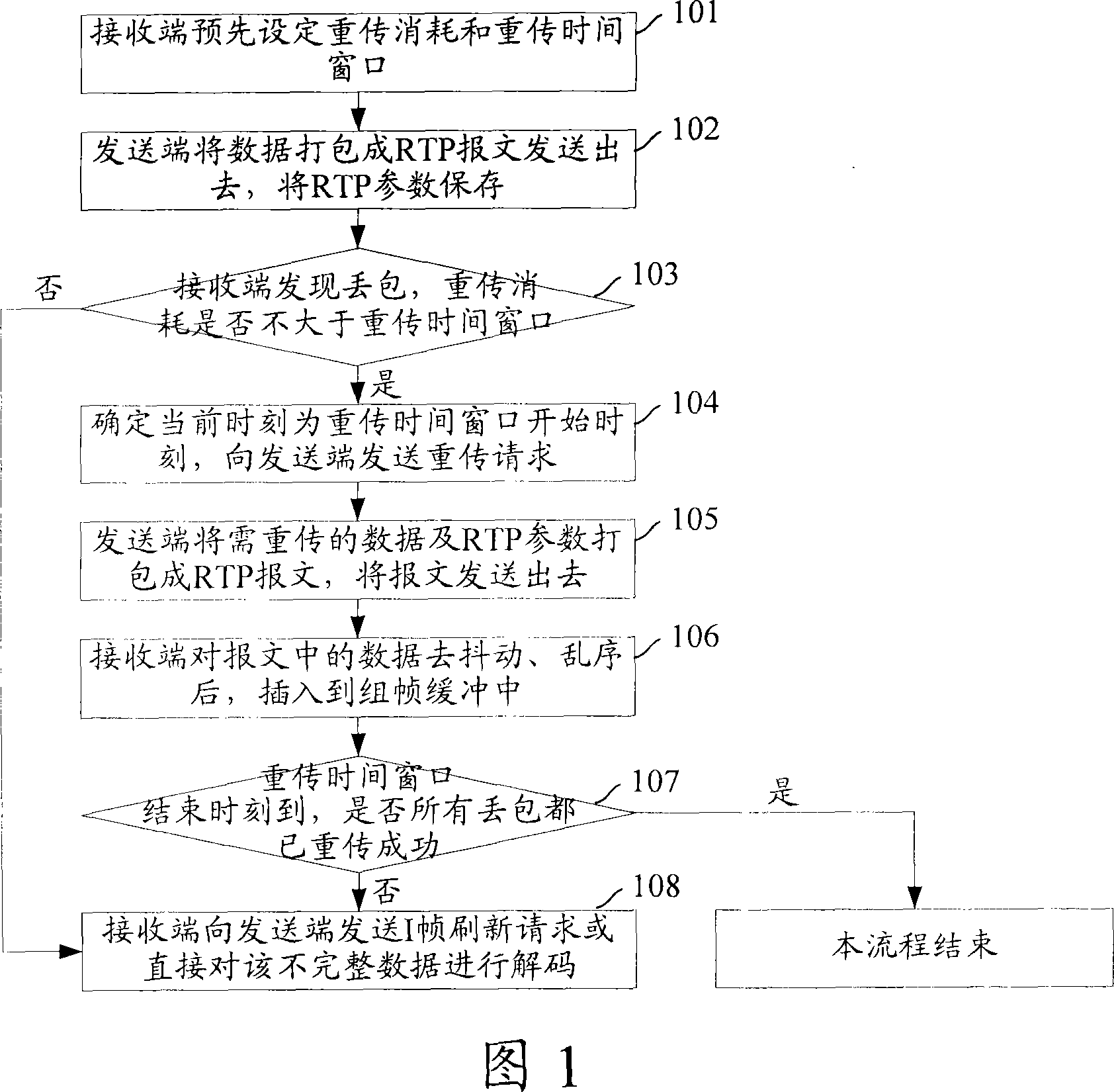
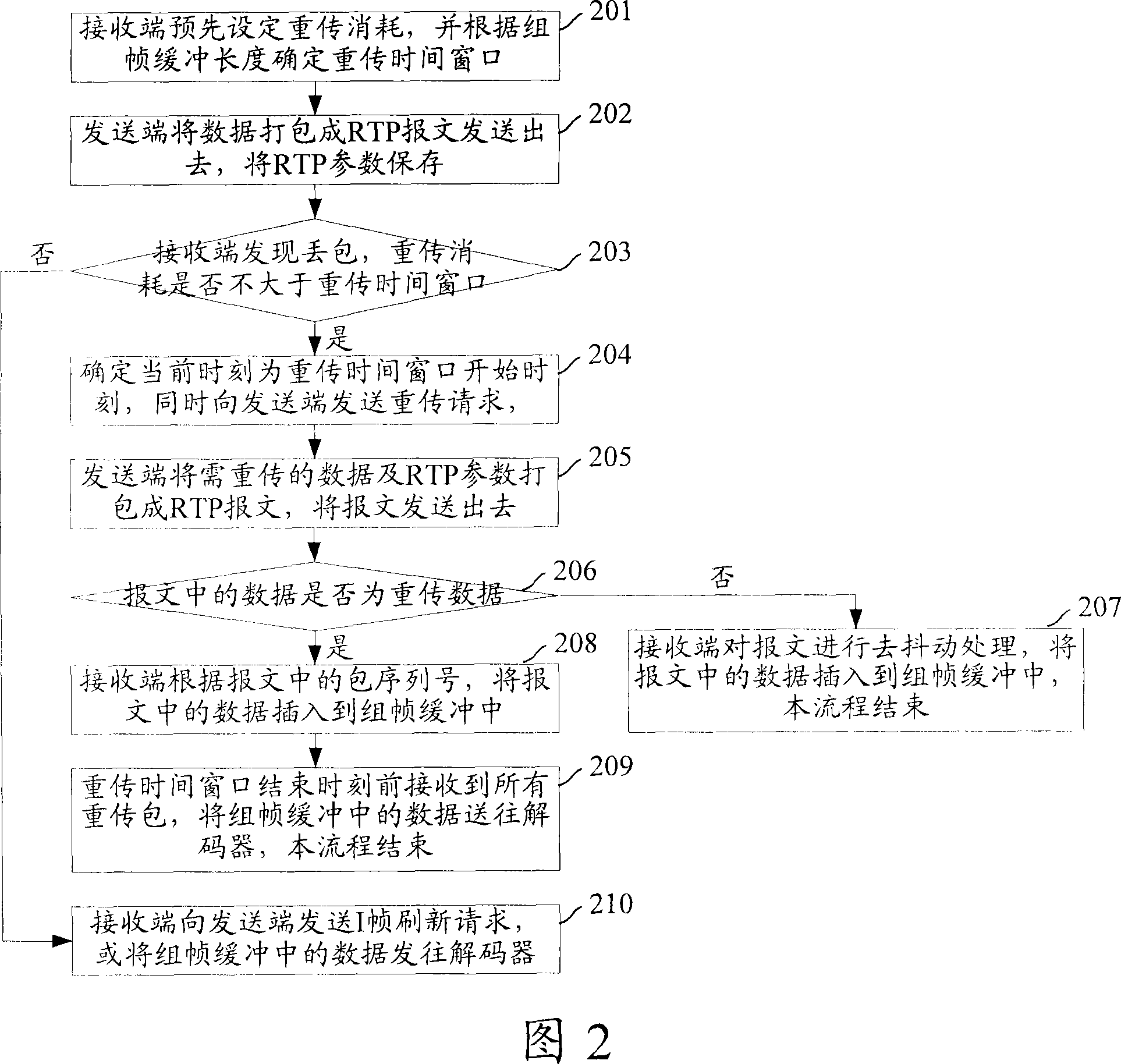
[0061] Embodiment 1: Satisfy playback continuity requirements in packet loss recovery.

[0062] Fig. 2 is the flowchart of recovering packet loss in real-time media stream transmission provided by Embodiment 1 of the present invention, as shown in Fig. 2, its specific steps are as follows:

[0063] Step 201: The receiving end presets the retransmission consumption, and determines the retransmission time window according to the length of the framing buffer.

[0064] Step 202 is the same as step 102 .

[0065] Step 203: The receiving end finds packet loss, and judges whether the retransmission consumption is not greater than the retransmission time window, and if so, executes step 204; otherwise, executes step 210.

[0066] Steps 204-205 are the same as steps 104-105.

[0067] Step 206: The receiving end receives the RTP message, and judges whether the data in the message is retransmission data according to the payload type value in the message header, and if so, executes step...

Embodiment 2

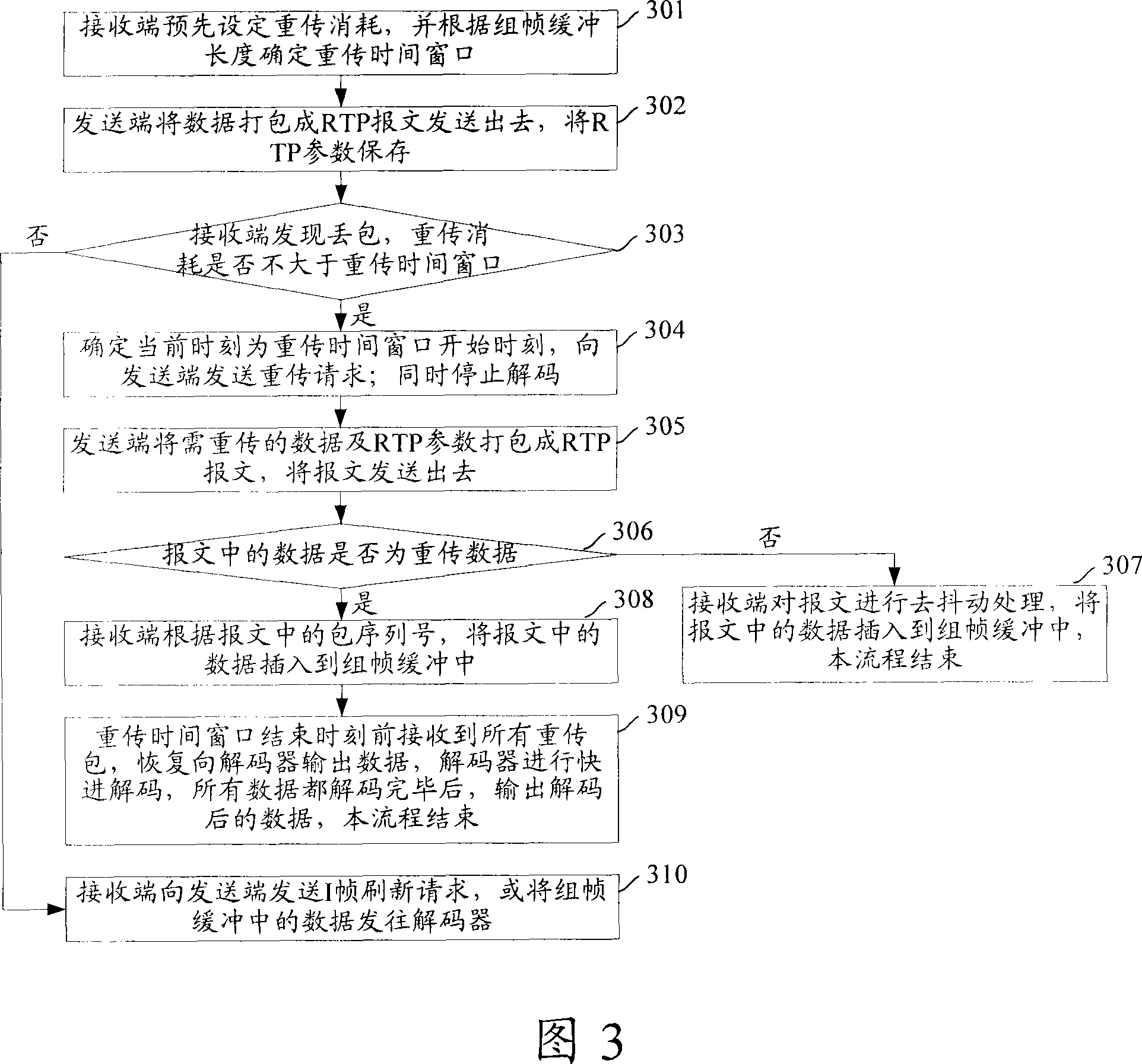
[0074] Embodiment 2, meeting the real-time requirement in packet loss recovery.

[0075] Fig. 3 is the flowchart of recovering packet loss in real-time media stream transmission provided by Embodiment 2 of the present invention, as shown in Fig. 3, its specific steps are as follows:

[0076] Step 301: The receiving end presets the retransmission consumption, and determines the retransmission time window according to the length of the framing buffer.

[0077] Step 302 is the same as step 102 .

[0078] Step 303: The receiving end finds packet loss, and judges whether the retransmission consumption is not greater than the retransmission time window, and if so, executes step 304; otherwise, executes step 310.

[0079] Step 304: The receiving end determines that the current time is the start time of the retransmission time window, and sends a retransmission request to the sending end. The request carries the data type to be retransmitted, the sequence number of the initial retran...

Embodiment 3

[0091] Embodiment 3: During packet loss recovery, the real-time requirement and playback continuity requirement are balanced.

[0092] Fig. 4 is the flowchart of recovering packet loss in real-time media stream transmission provided by Embodiment 3 of the present invention, as shown in Fig. 4, its specific steps are as follows:

[0093] Step 401: The receiving end presets the retransmission consumption, and determines the retransmission time window 1 according to the length of the primary framing buffer, and determines the retransmission time window 2 according to the length of the secondary framing buffer.

[0094] The retransmission time window 1 is: the time period from putting a non-retransmission packet into the first-level framing buffer to sending the packet to the second-level framing buffer.

[0095] The retransmission time window 2 is: the length of time consumed from putting a non-retransmission packet from the first-level framing buffer into the second-level framin...


PUM


Abstract

The invention discloses a real-time message packet loss recovery method, a real-time message packet loss recovery system and a receiving end unit. The method comprises that: the receiving end statistizes the time length consumed by packet retransmission (retransmission consumption), a time length consumed by a non-retransmitting packet from being placed into a framing buffer to being sent into a decoder is taken as a retransmission time window; the sending end packs the data into a real-time message, then sends the real-time message to the receiving end and stores the data at the same time; when the receiving end finds the packet loss, if that the retransmitting consumption is not greater than a retransmitting time window is confirmed, the receiving end sends a retransmitting request to the sending end, the current time is confirmed as the initial time of the retransmitting time window at the same time, the sending end packs the data which is stored and needs to be retransmitted into a message and then sends the message to the receiving end; the receiving end receives the retransmitted data sent by the sending end before the finish time of the retransmitting time window, the retransmitted data is inserted into the framing buffer. The invention reduces the network band width occupied by recovering packet loss under the premise of assuring the real time of data transmission.

Description

technical field [0001] The invention relates to the technical field of media transmission, in particular to a method, a system and a receiving end unit for recovering real-time packet loss in media stream transmission. Background technique [0002] Real-time media streaming has been applied in various fields such as: video conferencing system, monitoring system, IP television (IPTV) and so on. The current real-time media streaming uses the Real-time Transport Protocol (RTP, Real-timeTransport Protocol). RTP is a protocol that does not support any form of reliability guarantee and does not support any definition of congestion control. Therefore, RTP itself cannot recover from packet loss in real-time media streaming. [0003] Network packet loss will cause audio pauses, video blurs, and audio and video stops. At present, when the receiving end finds a video packet loss, it directly requests an I frame refresh from the sending end, and at the same time, stops decoding or dir...

Claims


Application Information

Patent Timeline
IPC IPC(8): H04L1/18H04L12/56H04L47/32
Inventor 罗奇勇余恒乐
Owner NEW H3C TECH CO LTD
Why Eureka
Try Eureka