
Wheel

A wheel and wheel body technology, applied in the direction of wheels, vehicle parts, transportation and packaging, etc., can solve problems such as high running noise

Inactive Publication Date: 2008-07-16
KUKA ROBOTER
View PDF1 Cites 18 Cited by
  • Summary
  • Abstract
  • Description
  • Claims
  • Application Information

AI Technical Summary

Problems solved by technology

[0003] Mecanum wheels of the prior art, especially when the roller bodies are mounted on wheel bodies with different diameters, have the disadvantage of high running noise

Method used


Image

  • Wheel
  • Wheel

Examples


Embodiment Construction

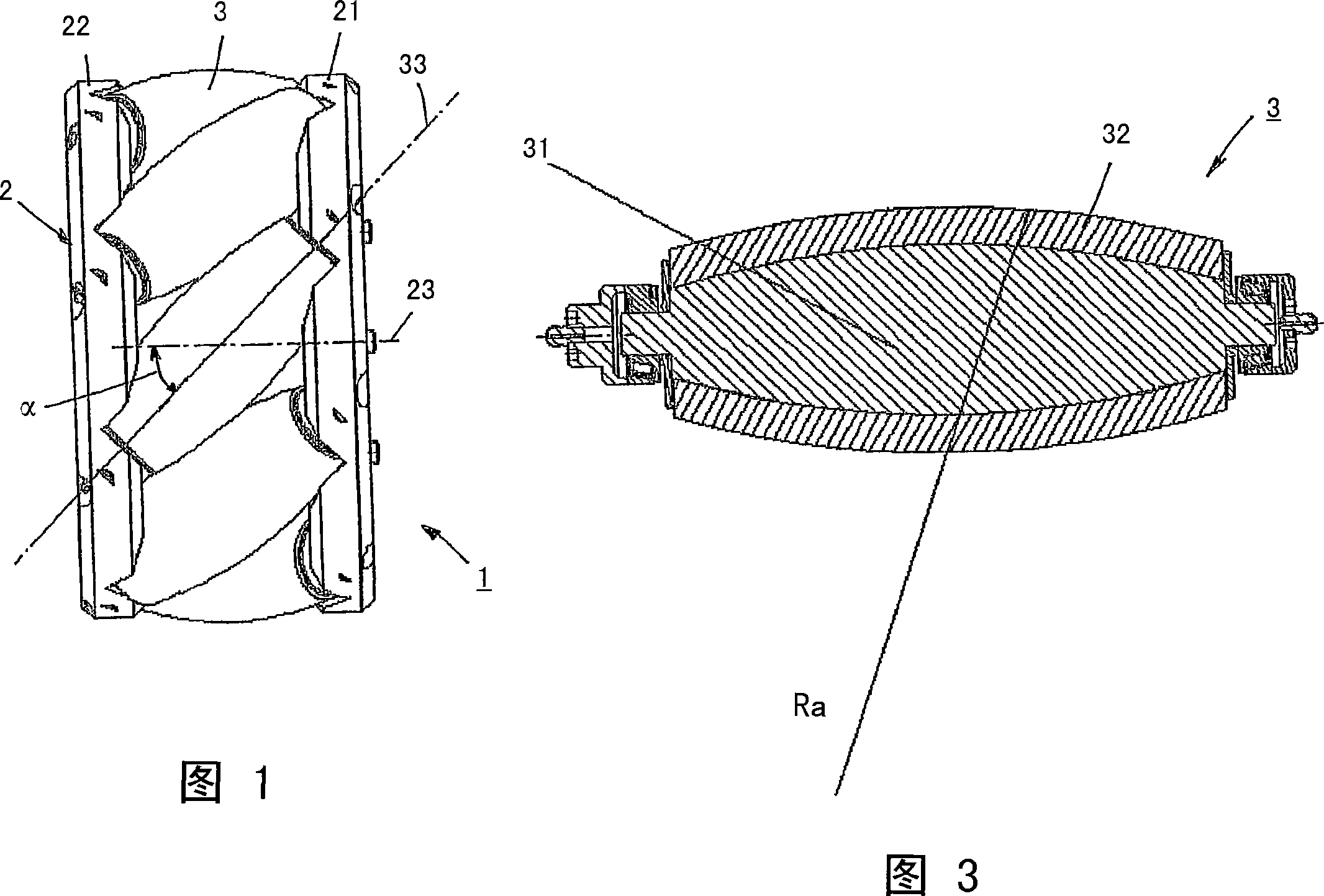
[0013] FIG. 1 shows a front view of a wheel 1 with a wheel body 2 having two support components 21 , 22 which are formed by discs spaced apart from one another. The support members 21, 22 can be driven by a drive device not shown and are fixedly connected to each other. The wheel body 2 is arranged to be rotatable in both directions about its axis of rotation 23 .

[0014] Between the support members 21 , 22 fixedly connected to each other, roller bodies 3 arranged equidistant from each other are arranged. The roller body 3 has a drum-shaped outer contour, and its rotation axis 33 forms an angle α with the rotation axis 23 of the wheel body 2 , preferably, α is 45°. The roller body 3 is freely rotatably arranged between the support members 21, 22, and the outer contour of the roller body 3 slightly protrudes beyond the outer periphery of the support members 21, 22, thereby forming a support for the wheel 1 on a foundation not shown. surface and rolling surface.

[0015] In ...


PUM


Abstract

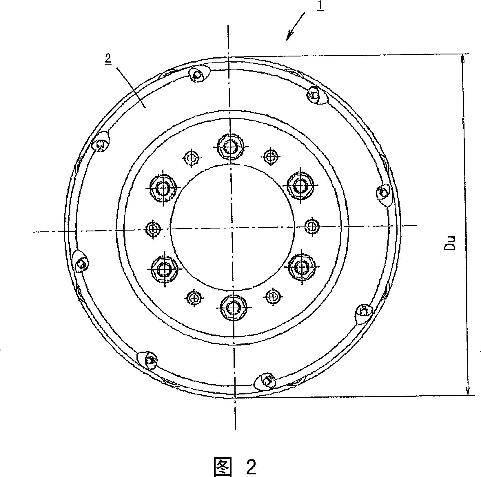
The invention relates to a wheel (1) with a driven wheel body (2), comprising two support elements (21, 22), between which a number of roller bodies (3) with a spherical surface are arrange to rotate, which at least partly extend beyond the circumference of the support elements (21, 22) the rotational axes of which are arranged at an angle to the rotational axis (23) of the wheel body (2). The ratio of the outer diameter (Du) of the wheel (1) to the maximum radius (Ra) of the roller body (3) is between 1.08 and 1.13, in particular, between 1.09 and 1.12.

Description

technical field [0001] The invention relates to a wheel with a driven wheel body having two supporting members between which a plurality of roller bodies having a ballig surface are rotatably arranged, said The roller body protrudes at least partially from the periphery of the support member, and its rotation axis is arranged obliquely to the rotation axis of the wheel body. Such wheels are particularly suitable for heavy-duty shunting locomotives (Schwerlastrangierfahrzeug). Background technique [0002] In the patent document DE 38 41 971 C2 there is disclosed a trackless floor conveyor which can maneuver in all directions (rangier bar) and is equipped with a subframe (Fahrschemel) on which deflecting rollers and driven wheels are mounted . The driven wheel has a drum-shaped or barrel-shaped roller body, and the rotating shaft of the roller body is arranged obliquely with the respective rotating shafts of the driven wheel. The driven wheels are known as "Mecanum wheels"...

Claims


Application Information

Patent Timeline
Patent Type & Authority Applications(China)
IPC IPC(8): B60B19/12
CPCB60B19/003B60B2360/324B60B2900/351B60B19/125
Inventor 沃尔夫冈·京特
Owner KUKA ROBOTER
Learn More