Dissection bone plate for locking wall agnail angle after acetabulum

A bone plate and acetabular technology, applied in the direction of outer plate, fixer, internal bone synthesis, etc., can solve the problems of large soft tissue damage, complicated fixation, medical accidents, etc., achieve easy placement and removal, reduce surgical incision, prevent Effects of Malpractice

Inactive Publication Date: 2008-07-23
张英泽
View PDF0 Cites 6 Cited by
  • Summary
  • Abstract
  • Description
  • Claims
  • Application Information

AI Technical Summary

Problems solved by technology

The disadvantages of this method are: the anatomical shape of the acetabular part is complicated, the fracture types are complicated, and the effect of only relying on a long reconstruction plate with a single row of screws is not ideal.
When using multiple bone plates for fixation at the same time, because the bone plates are independent, the fixation of complex fractures is often not reliable; using multiple bone plates, the fixation is complicated, and the soft tissue is greatly damaged; in addition, the use of multiple bone plates Fixed surgical costs are expensive, increasing the economic burden on patients and society
At the same time, the existing steel plate is in the shape of a flat plate. When using it, it is necessary to bend the steel plate into an arc close to the fracture site with the help of instruments or by hand, which is inconvenient to use
On the other hand, since the center line of the screw hole on the steel plate is perpendicular to the plate surface, the end of the screw is easy to enter the acetabulum when the screw is screwed on, which hinders the movement of the joint and even causes medical accidents.

Method used


Image

  • Dissection bone plate for locking wall agnail angle after acetabulum

Examples


Embodiment Construction

[0019] The present invention will be further described in detail below in conjunction with the accompanying drawings of the embodiments.

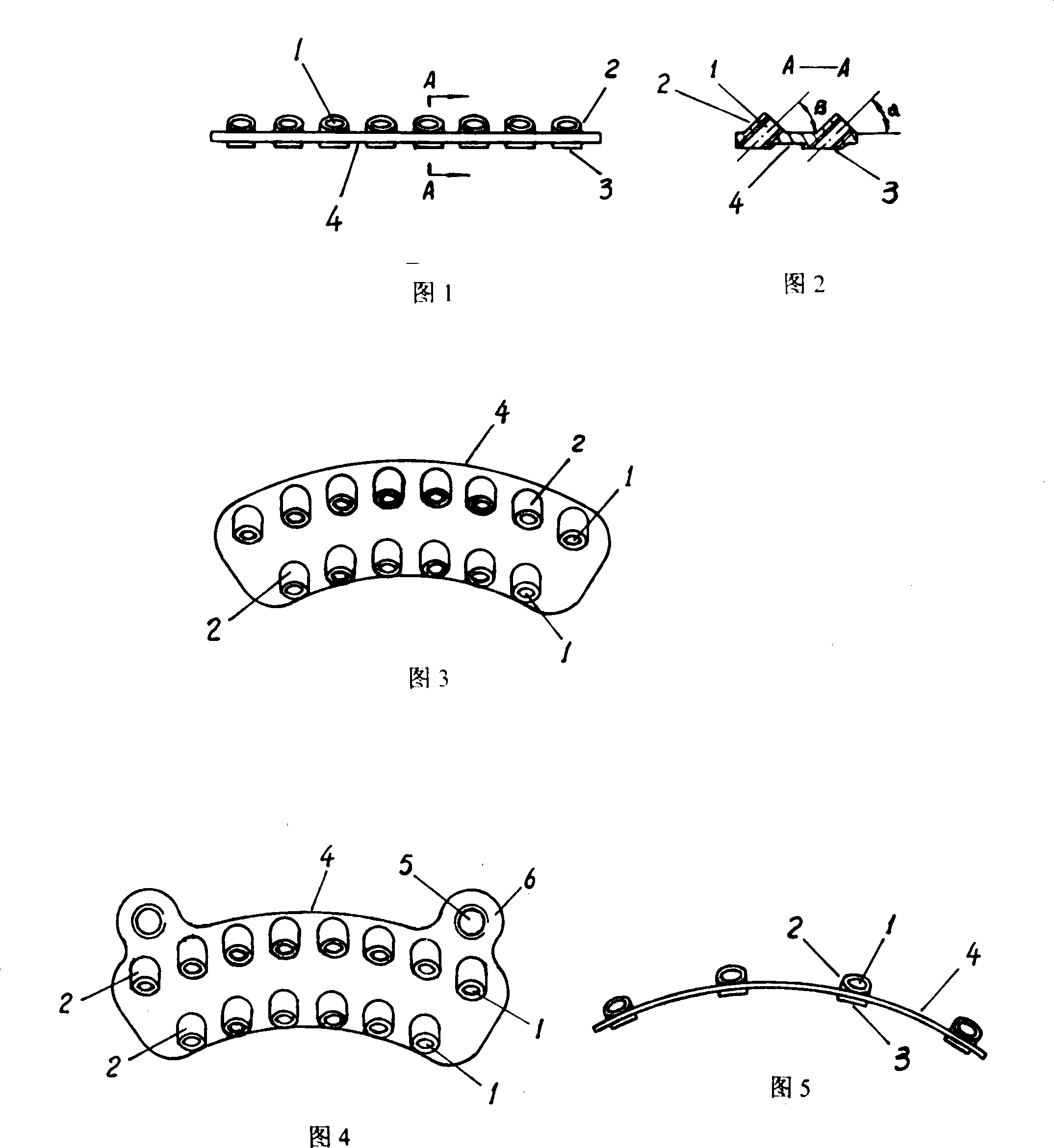
[0020] Referring to Fig. 1-Fig. 3, in embodiment one, plate body 4 is flat fan-shaped plate, adopts medical stainless steel to make, and steel plate thickness is 0.8-2mm, and width is 20-25mm, and length is 40-70mm, and screw hole 1 Bosses are provided on both plate surfaces of the site, the height of the boss 3 on the side that is in contact with the bone surface is 0.5mm, and the height of the boss 2 on the other side is 1mm. The plate body 4 is provided with two rows of screw holes 1, the number of screw holes 1 on the side of the plate body 4 opposite to the acetabular rim is 6, and the number of screw holes 1 on the opposite side is 8. The screw holes 1 can all be through holes, or all can be threaded holes, but preferably the through holes and the threaded holes are arranged alternately. The advantage of the screw hole being a throug...


PUM


Abstract

An acetabulum posterior wall angle locking anatomic bone plate pertains to the technical field of surgical medical devices. The invention provides the acetabulum posterior wall angle locking anatomic bone plate which has small surgical incision, safe and reliable fixation and is conductive to the healing of fracture. The invention includes a plate body which is provided with screw holes, the screw holes are two rows of oblique holes, which are respectively arranged along one side of the plate body which is opposite to the edge of the acetabulum and the opposite side, the oblique included angle Alpha of the central line of the screw holes which are arranged at the one side of the plate body which is opposite to the edge of the acetabulum and the plate surface is 30 degrees to 45 degrees, and the oblique included angle Beta of the central line of the screw holes at the opposite side and the plate surface is 30 degrees to 60 degrees. The invention can make use of the self-shape to ensure the fixation of fracture to be most close to the normal structure after the reduction and fixation of the fracture. The invention has the integrity and the stability which are not possessed by the combined usage of a plurality of bone plates. The invention can reduce surgical incision, reduce the dissection of soft tissues, have less oppression on the periosteum and be more conductive to the healing of fracture. The placement and the removal are easy, and the cost is low. When a screw is screwed, the rod part of the screw can accurately avoid the acetabulum.

Description

technical field [0001] The invention relates to an acetabular posterior wall angle-locked anatomical bone plate, which belongs to the technical field of surgical instruments. Background technique [0002] An important step in the treatment of posterior acetabular fractures is reduction and fixation of the fracture. At present, the commonly used fixation method is to place the back of the acetabulum with one or more reconstruction plates at predetermined positions, and then use fixation screws to pass through the screw holes on the bone plate to anatomically reduce and fix the fracture. The disadvantage of this method is that the anatomical shape of the acetabular part is complex and the types of fractures are complex, and the effect of fixation with a single row of screws on a long reconstruction plate is not ideal. When using multiple bone plates for fixation at the same time, because the bone plates are independent, the fixation of complex fractures is often not reliable;...

Claims


Application Information

Patent Timeline
Patent Type & Authority Applications(China)
IPC IPC(8): A61B17/80
Inventor 张英泽张国川李西成
Owner 张英泽
Why Eureka
Try Eureka