Drafting assembly of spinning machine

A drafting device and spinning machine technology, applied in spinning machines, drafting equipment, textiles and papermaking, etc., can solve problems such as high pressure on the cradle, increased drafting force, unevenness, etc.

Inactive Publication Date: 2008-07-23
HEBEI TAIHANG TEXTILE MACHINERY CO LTD
View PDF0 Cites 8 Cited by
  • Summary
  • Abstract
  • Description
  • Claims
  • Application Information

AI Technical Summary

Problems solved by technology

The existing drafting device has the following problems: 1. The size of the working gear of the relevant drafting devices such as aprons, top rollers, and rollers is too large, so that the friction area between the contacting rollers, top rollers and aprons increases accordingly Large, the cradle pressure associated with it is also relatively large
Studies have shown that the width of the working area required by the strands during the drafting process does not exceed 12 mm, and the larger working size of the drafting device will increase the corresponding drafting force in addition to wasting materials, resulting in equipment energy and material damage. Large consumption; 2. The wrap angle between the bottom roller and the bottom apron is 65°~87°, which is obviously too small
As we all know, the smaller the wrap angle, the shorter the contact arc between the roller and the lower apron, and the smaller the total friction force generated by the contact surface, so the middle and lower rollers need to have a greater driving force, which is causing draft Another reason for the large power loss of the device; 3. The elastic floating jaws and the drafting area have poor control over the sliver fibers, which increases the unevenness of the evenness and affects the quality of the yarn

Method used


Image

  • Drafting assembly of spinning machine
  • Drafting assembly of spinning machine
  • Drafting assembly of spinning machine

Examples


Embodiment Construction

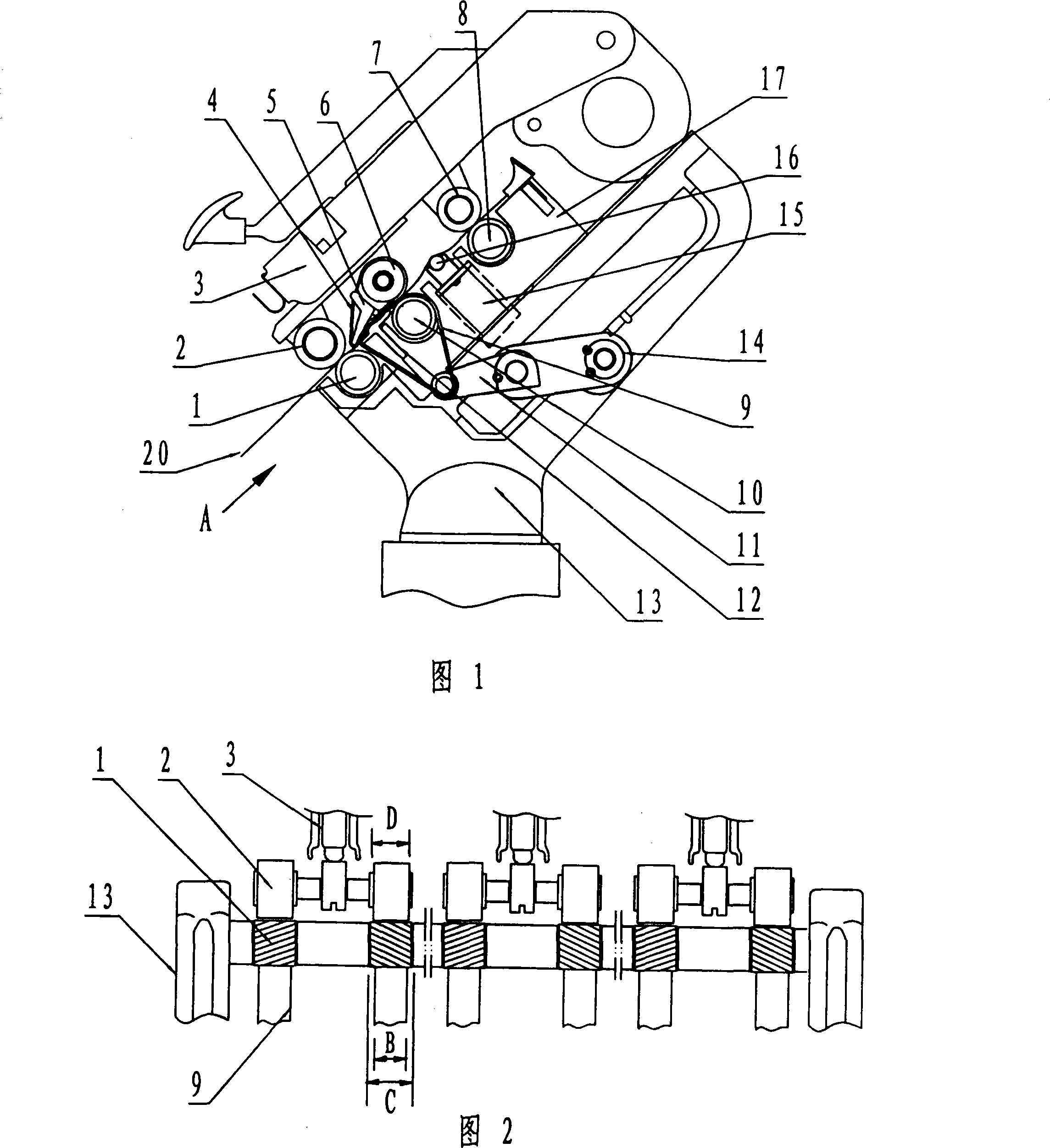
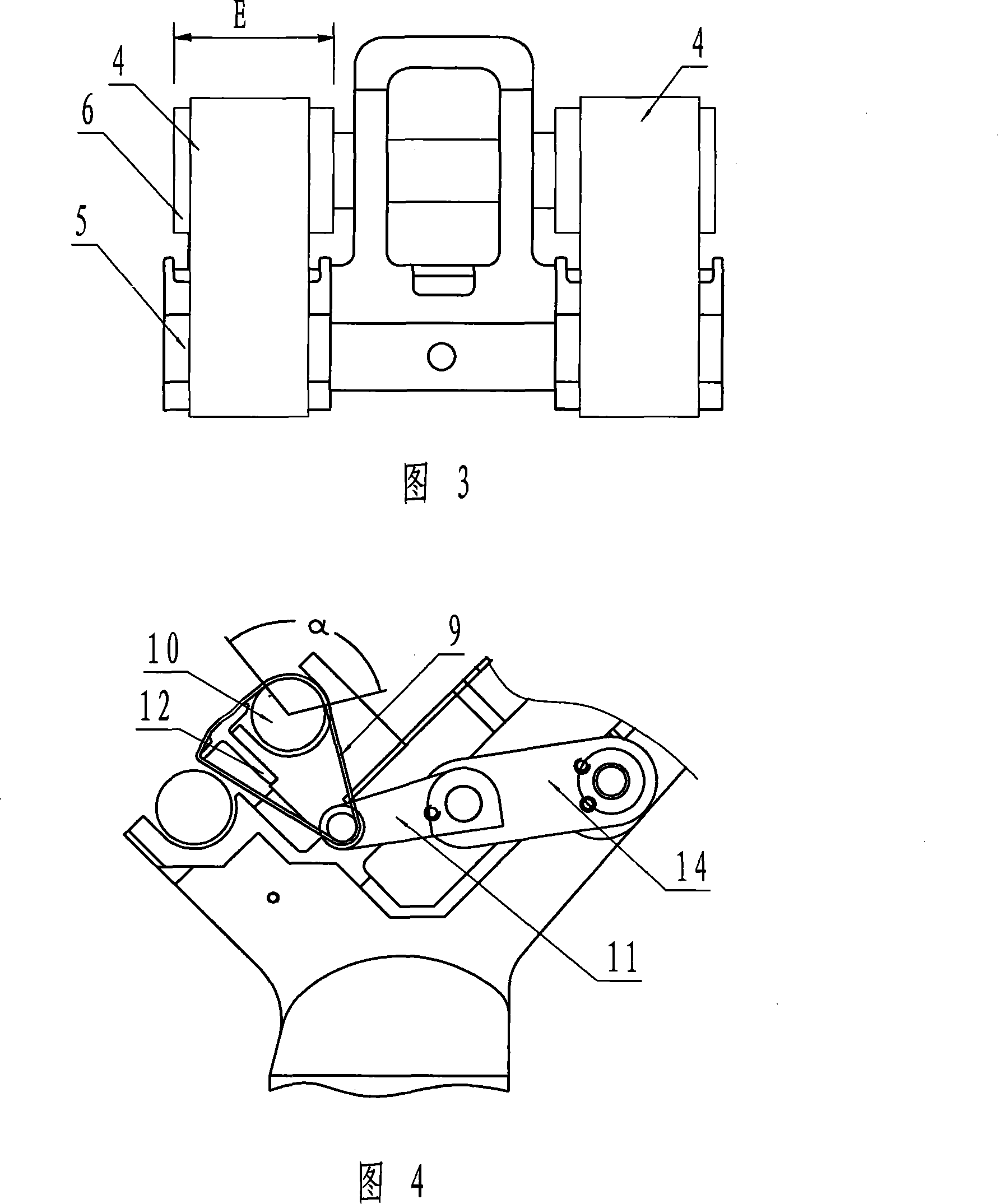
[0022] Referring to Fig. 1~Fig. 3, in the composition of the present invention, comprise the front top roller 2, front bottom roller 1 that are positioned at the front portion of the drafting zone; The main drafting assembly in the middle, the main drafting assembly is made up of middle upper roller 6, upper pin 5, upper apron 4 surrounding the above two, middle and lower roller 10, lower pin 12, and lower apron 9 surrounding the above two. The front top roller, the rear top roller and the upper pin assembly are all positioned on the cradle 3; the front bottom roller, the rear bottom roller and the middle bottom roller are all positioned on the roller stool 13. In order to reduce the friction loss, the present invention optimizes the size of the relevant drafting device as follows: the working gear size D of the front top roller and the rear top roller is 15-28 mm, and the front bottom roller, the middle bottom roller and the rear bottom roller work gear The dimension C is 15-...


PUM

PropertyMeasurementUnit
widthaaaaaaaaaa
widthaaaaaaaaaa

Abstract

The invention relates to a drafting device of a spinning machine, belonging to the spinning technical field, comprising a cradle, a plurality of rollers, a front lower roller, a front upper rubber roller, a back upper rubber roller, a back lower roller and a main drafting component, wherein, the front lower roller and the front upper rubber roller are arranged at the front section of a drafting area, the back upper rubber roller and the back lower roller are arranged at the back area of the drafting area, and the main drafting component is arranged at the central section of the drafting area, the main drafting component comprises a middle upper roller, an upper pin, an upper leather collar, a middle lower roller, a lower pin and a lower leather collar. After improvement, the working position dimension D of the front upper rubber roller and the back upper rubber roller are 15 to 28 millimeters, the working position dimension C of the front lower roller and the middle lower roller and the back lower roller are 15 to 32 millimeters, the width dimension B of the upper leather collar and the lower leather collar are 14 to 27.5 millimeters, the width dimension E of the middle upper roller is 15 to 30 millimeters. The drafting device of the spinning machine has the advantages of reducing the friction area and the driving power, improving the operation stability of the drafting component, saving lots of consumable materials, effectively reducing the production cost and improving the quality of resultant yarn.

Description

technical field [0001] The invention relates to a textile machine, in particular to a drafting device for a spinning machine which can effectively reduce energy consumption and stably control sliver fibers, and belongs to the technical field of textiles. Background technique [0002] The function of the spinning frame in textile machinery is to draft the roving, that is, through three pairs of rollers with different speeds in the drafting device, the roving fibers are evenly and stably stretched and thinned, and then twisted to form a spun yarn. In the double-zone drafting system for spun yarn, the fiber speed is changed under the control of the front and rear friction circles to complete the drafting. Among them, the drafting components located at the rear and the front are simple roller drafting composed of top rollers and bottom rollers, and the main drafting components located in the middle are composed of middle top rollers, top pins and wrapping around the middle top r...

Claims


Application Information

Patent Timeline
Patent Type & Authority Applications(China)
IPC IPC(8): D01H5/18D01H5/74D01H5/86D01H5/46
Inventor 张晓方陆惠文
Owner HEBEI TAIHANG TEXTILE MACHINERY CO LTD
Why Eureka
Try Eureka