Triangle mechanism of computer plain flat knitter

A technology of flat knitting machine and needle guard triangle, which is applied in knitting, weft knitting, textiles and papermaking, etc. It can solve the problems of strict processing precision of needle jack 17, increase of manufacturing cost, and increase of overall machine volume, etc., and achieves The volume of the whole machine is reasonably reduced, the width of the machine head is reduced, and the effect of needle movement is guaranteed

Inactive Publication Date: 2008-07-23
常熟市碧溪新区和宝纺织机械厂
View PDF2 Cites 17 Cited by
  • Summary
  • Abstract
  • Description
  • Claims
  • Application Information

AI Technical Summary

Problems solved by technology

[0009] As can be seen from the above description, as far as the structure of the triangular mechanism itself is concerned, it is very complicated, and it also leads to the complexity of the knitting needle assembly, so that the knitting needle assembly also needs to be composed of six segment selection pins 15, push needles, except the knitting needle 16. Sheet 17 and push sheet 18, these four parts must be used at the same time, and one is indispensable, so it brings the following shortcomings: First, the needle bed and machine head of the computerized flat knitting machine must be kept to a sufficient width, thereby increasing the overall width. The volume of the machine increases the manufacturing cost; secondly, from the applicant's description of the knitting principle, whether the knitting needle 16 performs knitting, transfer, tuck, and stitching depends on whether the push piece 18 is pressed by a non-woven 23. The tuck pressing piece 24, or the left and right needle pressing piece 26L, 26R is pressed into the needle groove. When the push piece 18 is pressed into the needle groove, ...

Method used


Image

  • Triangle mechanism of computer plain flat knitter
  • Triangle mechanism of computer plain flat knitter
  • Triangle mechanism of computer plain flat knitter

Examples


Embodiment Construction

[0030] In order to enable the examiners of the patent office, especially the public, to further understand the technical essence and beneficial effects of the present invention, the specific implementation methods of the present invention are described in detail below in conjunction with the accompanying drawings and examples. However, the applicant declares that any formal changes or textual modifications based on the concept of the present invention shall be regarded as the scope of the technical solutions of the present invention.

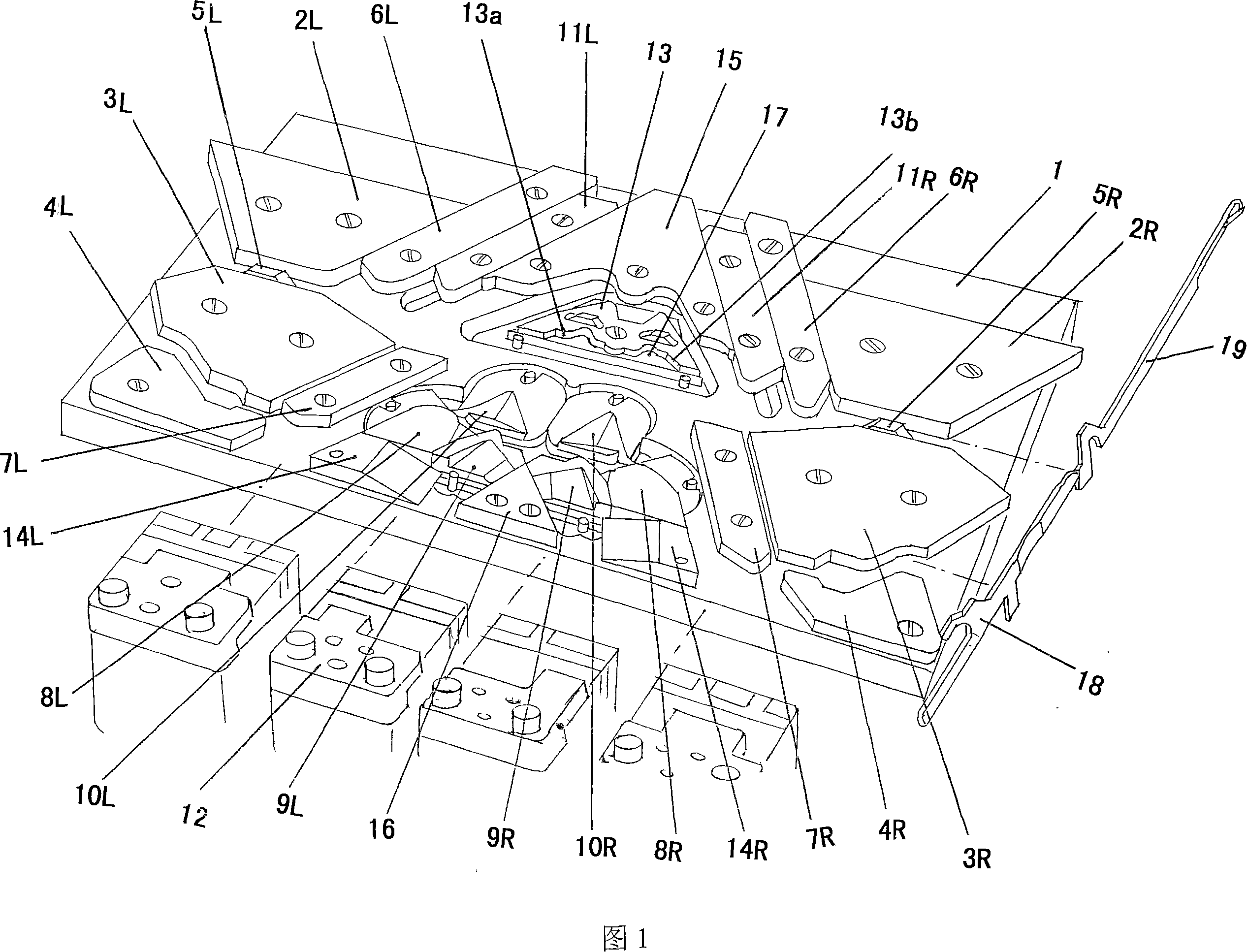
[0031] Please see Fig. 1, a triangular bottom plate 1 is provided, which is installed on the machine head of the knitting mechanism of the computerized flat knitting machine. The machine head has front and rear points, so the triangular bottom plate 1 has a pair of The industry is called the front and rear triangular bottom plates. The following statements are only for a triangular base plate 1, the knitting needles of the knitting needle assemb...


PUM


Abstract

The invention relates to a cam apparatus for a computer flat knitting machine belonging to the knitting machine technical field, which comprises a cam base, a first, a second and a third left and right external horizontal cams and outer left and right pressing cams, a left and a right needle limit cams, a left and a right pin limit cams and a group of needle selecting devices arranged on the cam base; a needle turning cam, a pair of left and right pin needle turning cylinder cams, a pair of left and right tuck cams, a pair of left and right needle connecting cams, a pair of left and right jack knitting cams and a pair of left and right density cams arranged on the cam base. The cam apparatus is characterized in that a guard against error cam and a selective tucking cam are also fixed on the cam base; the guard against error cam is arranged above the cam base and between the left and the right density cams; the selective tucking cam is arranged below the central section of the cam base and contacts with the left and the right needle connecting cams. The cam apparatus for a computer flat knitting machine has the advantages of simple structure, easy manufacturing and assembly, compact size of the completer machine, less abrasion, non-harsh processing requirements and no firing pin.

Description

technical field [0001] The invention belongs to the technical field of knitting machinery, and in particular relates to a triangle mechanism of a computerized flat knitting machine. Background technique [0002] The triangular mechanism of the computer knitting flat knitting machine in the prior art is shown in Figure 8, and the following description is for two systems, including the triangular bottom plate 14; The stitching cam 5, the transfer cam 20, the first, the second, the third, the fourth needle guide cams 8, 9, 10, 11 and the first, second, third, and the first, the second, the third, and the first of the two stitching bevels 5a, 5b Four left guide pin cams 8L, 9L, 10L, 11L and the first, second, third and fourth right guide pin cams 8R, 9R, 10R, 11R; needle jack cams that can enter and exit vertically on the triangular base plate 14 respectively 2, transfer cam 3; the left and right density cams 4L, 4R that can slide parallel to the triangular base plate 14; the s...

Claims


Application Information

Patent Timeline
IPC IPC(8): D04B15/36
Inventor 邵爱明
Owner 常熟市碧溪新区和宝纺织机械厂
Why Eureka
Try Eureka