Essence tracing subsystem for laser communication tracking system

A tracking system and laser communication technology, which is applied in the field of fine tracking subsystems, can solve the problems of small working range, easy loss of light source, and high cost, and achieve the effects of large working range, expanded tracking range, and low cost

Inactive Publication Date: 2008-07-23
CHANGCHUN UNIV OF SCI & TECH
View PDF0 Cites 14 Cited by
  • Summary
  • Abstract
  • Description
  • Claims
  • Application Information

AI Technical Summary

Problems solved by technology

The fine tracking subsystem in the existing laser communication tracking system is driven by piezoelectric ceramics, that is, PZT. As shown in Figure 1, the system uses a two-dimensional PZT driver 9 to drive a two-dimensional tilting mirror 10. The tilting mirror 10 reflects the incident laser beam 8 to the four-quadrant photodetector 11, converts the optical signal into an electrical signal through the four-quadrant photodetector 11 and sends it to the control system 12, and then the control system 12 outputs the control signal to the two-dimensional PZT driver 9. The position of the two-dimensional tilting mirror 10 is adjusted by the two-dimensional PZT driver 9, thereby realizing precise tracking of the laser source; the advantages of the system in Figure 1 are small size, high precision, and fast response speed; the disadvantage is that the working range is small, and currently The maximum working range of the PZT type high-precision tracking system is 7′, it is easy to lose the light source, and the cost is very high

Method used


Image

  • Essence tracing subsystem for laser communication tracking system

Examples


Embodiment Construction

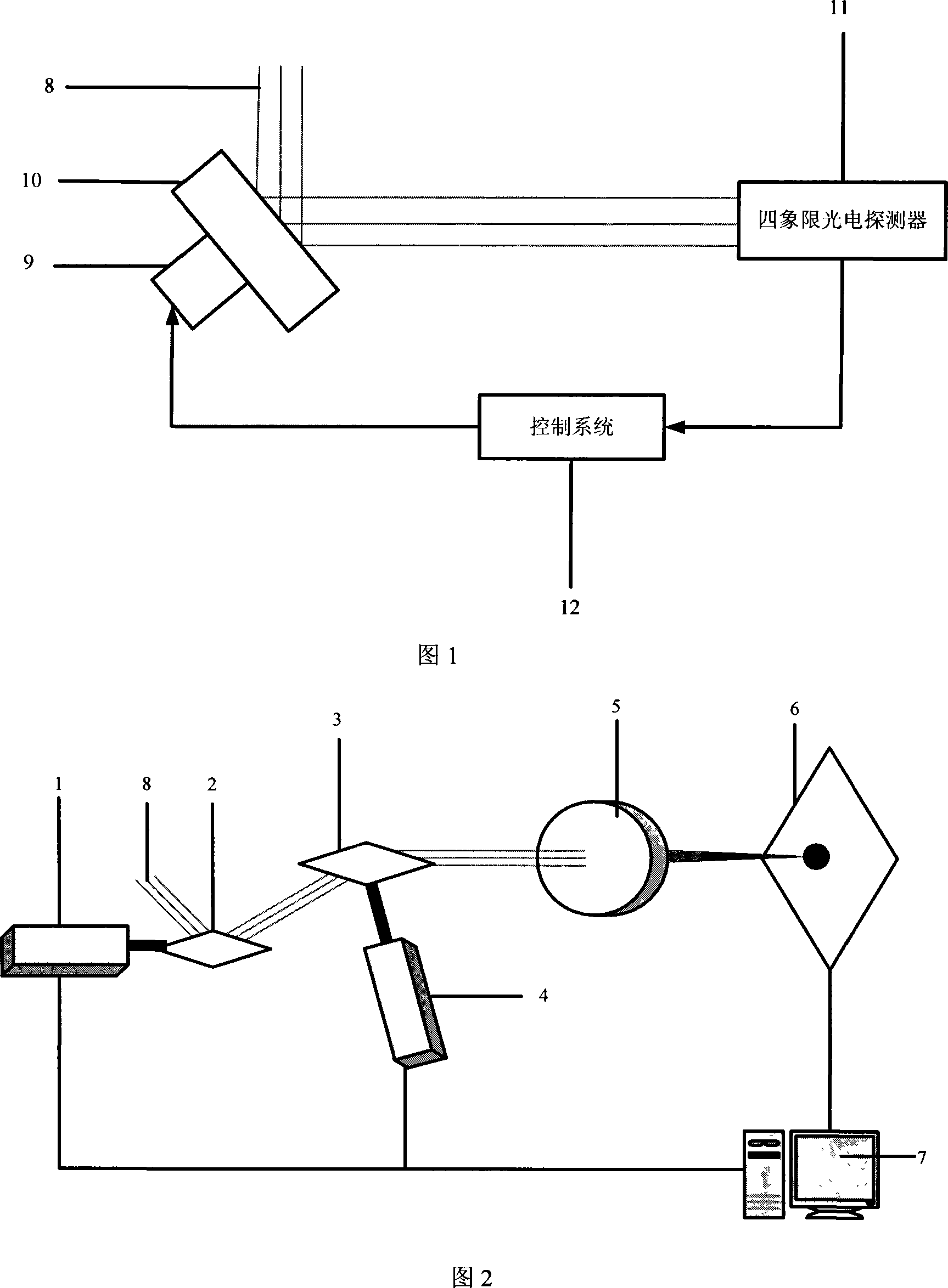
[0007] The structure shown in accompanying drawing 2 is an embodiment of the present invention. In the figure, 1 is the TL-8203 vibrating mirror motor, 2 is the Φ12 scanning mirror, 3 is the Φ12 scanning mirror, 4 is the TL-8203 vibrating mirror motor, 5 is the F-θ lens with a focal length of 30mm, and 6 is the M60 high frame rate camera , 7 is the control system, 8 is the incident laser beam.

[0008] After the system completes the rough tracking work, the laser beam entering the fine tracking system uses the galvanometer motor 1, scanning mirror 2, scanning mirror 3, and galvanometer motor 4 to form a two-dimensional galvanometer group to complete the position movement in the two-dimensional space. The dimensional vibrating mirror group and the F-θ lens 5 form a new fine-tuning mechanism. The F-θ lens 5 converges the laser beam and images it on the high frame rate camera 6. The high frame rate camera 6 detects the spot position after focusing, and the controller 7 pairs The...


PUM


Abstract

The invention relates to an accurate track subsystem of free space laser communication system, which comprises a lens vibration motor 1, a scanning mirror 2, a scanning mirror 3, a lens vibration motor 4, a F-theta lens 5, a high frame frequency camera 6 and a control system 7. The invention uses the motor 1, scanning mirror 2, scanning mirror 3, and motor 4 to form a two-dimension lens vibration assembly to realize the motion in two-dimension space, and uses the two-dimension lens vibration assembly and the F-theta lens 5 to form a new fine adjustment mechanism to expand track range, with confirmed track precision and track speed, while the maximum track range can reach +-5 degrees and the cost is reduced 35-40%.

Description

technical field [0001] The invention relates to a fine tracking subsystem in a free space laser communication system Background technique [0002] The laser communication tracking system is divided into two subsystems, a rough tracking system and a fine tracking system, and the present invention is the fine tracking subsystem in the laser communication tracking system. The fine tracking subsystem in the existing laser communication tracking system is driven by piezoelectric ceramics, that is, PZT. As shown in Figure 1, the system uses a two-dimensional PZT driver 9 to drive a two-dimensional tilting mirror 10. The tilting mirror 10 reflects the incident laser beam 8 to the four-quadrant photodetector 11, converts the optical signal into an electrical signal through the four-quadrant photodetector 11 and sends it to the control system 12, and then the control system 12 outputs the control signal to the two-dimensional PZT driver 9. The position of the two-dimensional tilting...

Claims


Application Information

Patent Timeline
Patent Type & Authority Applications(China)
IPC IPC(8): G02B26/10H04B10/00
Inventor 姜会林张立中李永亮孟立新
Owner CHANGCHUN UNIV OF SCI & TECH
Why Eureka
Try Eureka