Visual sense analogy method for dynamic false contour effect of pair field display device

A display device and visual simulation technology, applied in the direction of identification device, static indicator, cathode ray tube indicator, etc., can solve the problem that DFC is not objective and effective

Inactive Publication Date: 2008-07-23
IRICO
View PDF0 Cites 1 Cited by
  • Summary
  • Abstract
  • Description
  • Claims
  • Application Information

AI Technical Summary

Problems solved by technology

Until now, there is no more objective and effective method for evaluating the effect of improving the DFC of pictures or images

Method used


Image

  • Visual sense analogy method for dynamic false contour effect of pair field display device
  • Visual sense analogy method for dynamic false contour effect of pair field display device
  • Visual sense analogy method for dynamic false contour effect of pair field display device

Examples


Embodiment Construction

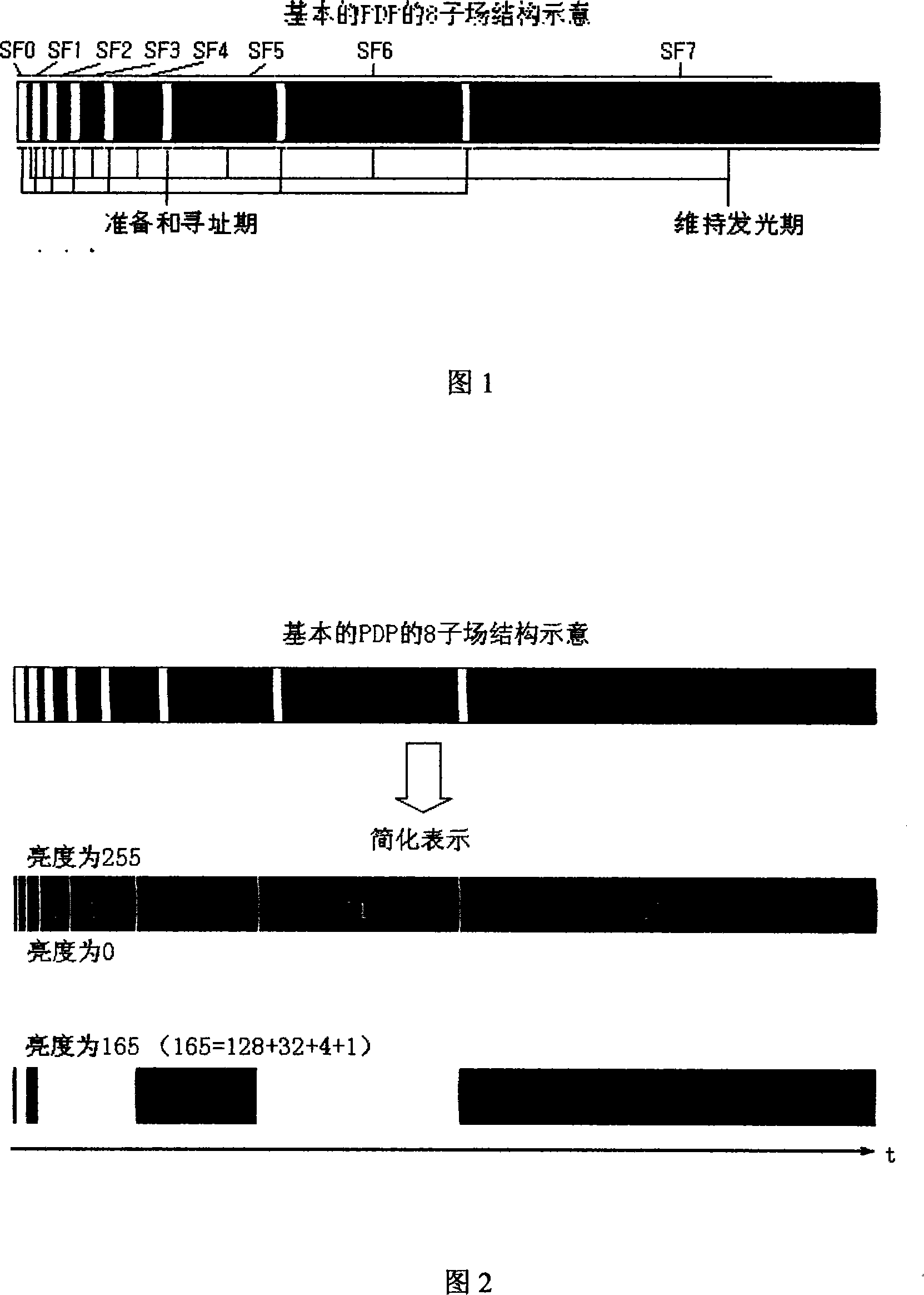
[0027] The subfield display parameters in the driving technology of PDP, that is, the number of subfields used, the weighted value of subfields, the maintenance display time length and interval of subfields, and the change control methods of various unique technologies for subfields can all be measured or can be designed and quantified;

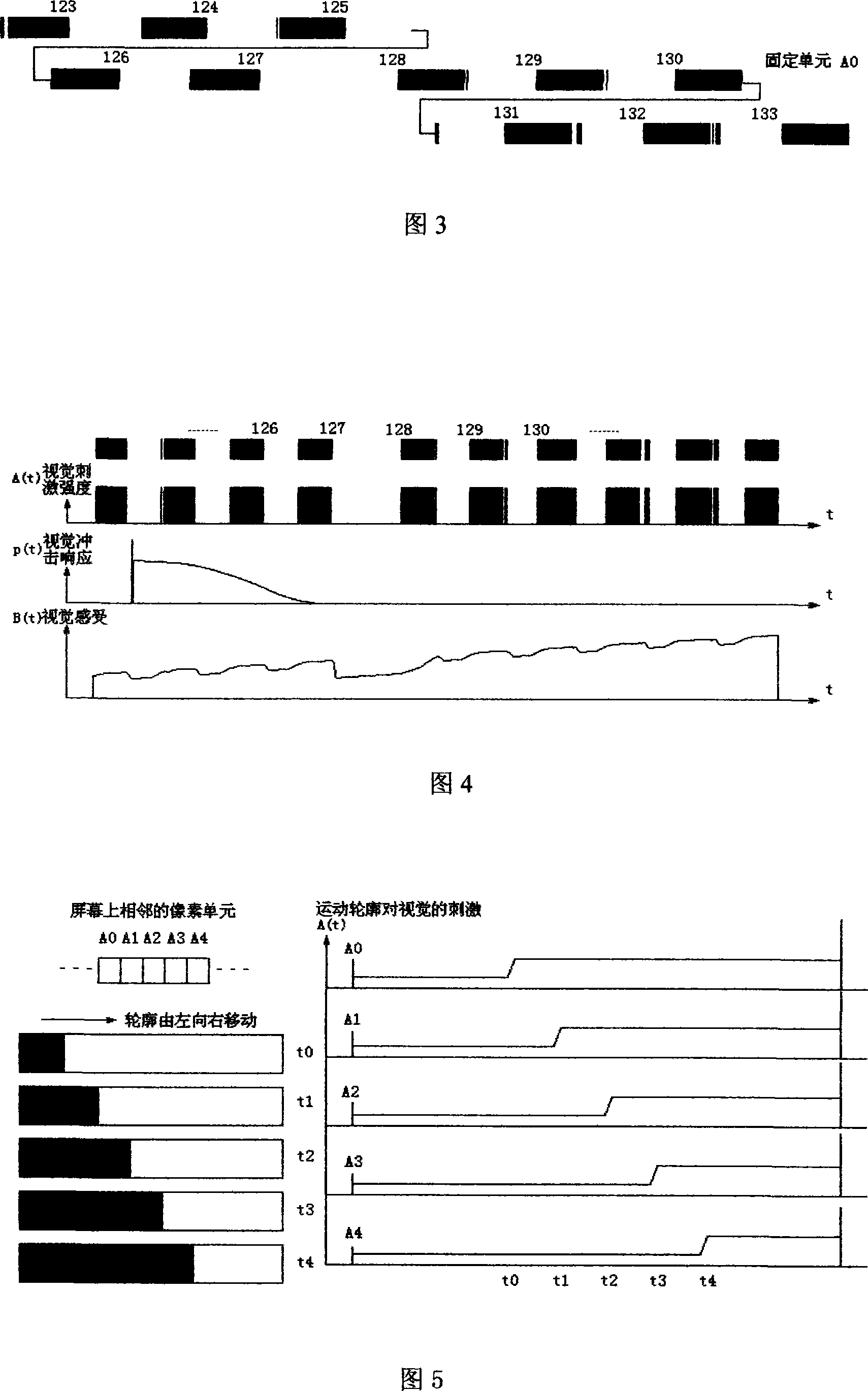
[0028] The visual response characteristic curve (visual model) of the human eye to the brightness impulse signal input based on the statistical law has been confirmed.

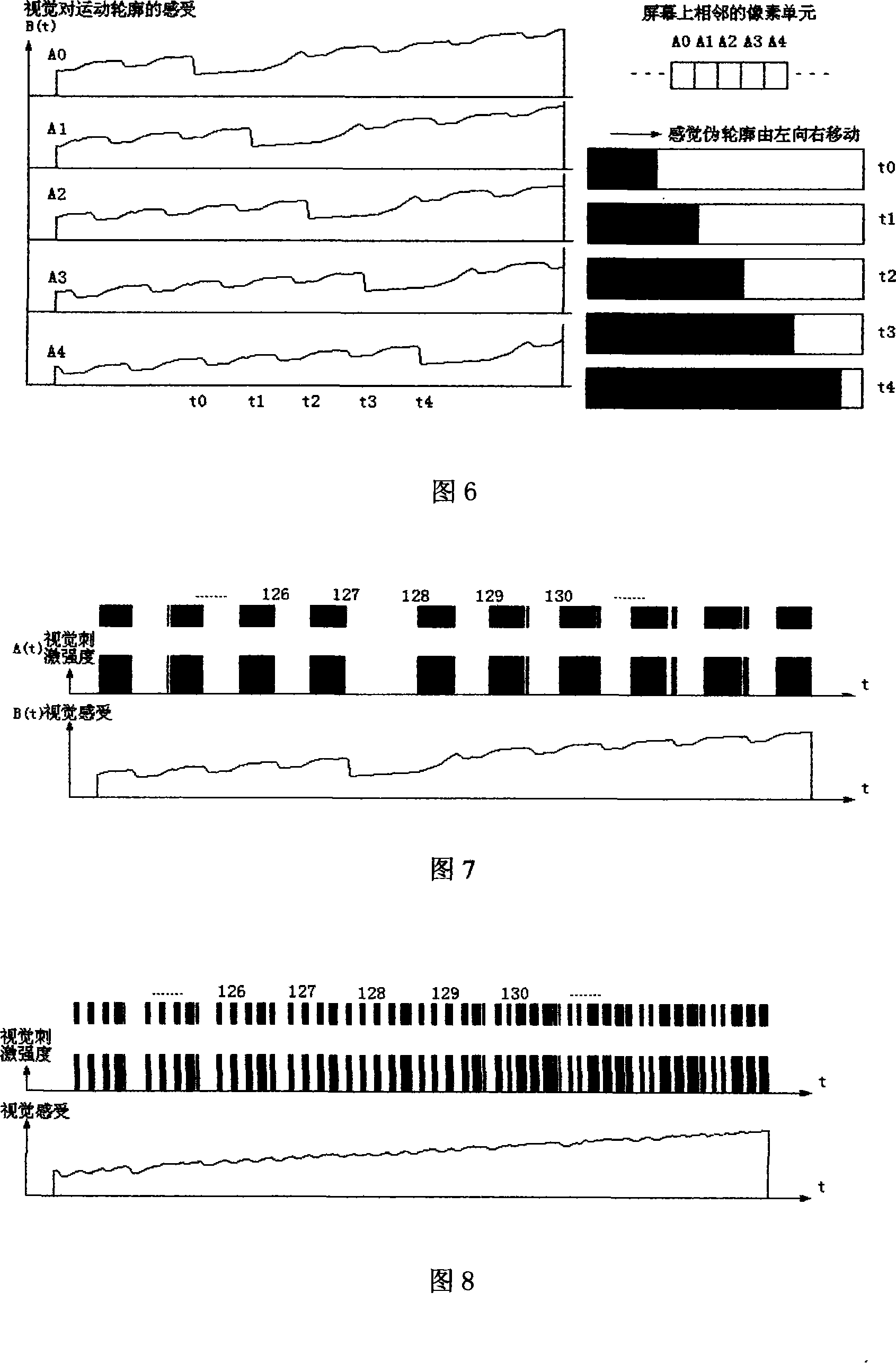
[0029] The response of the human eye to a scene or picture can be regarded as the mathematical convolution result of the light input of the scene and the visual impulse response characteristic.

[0030] In actual use, due to the characteristics of binocular viewing, human eyes are more sensitive to DFC in the horizontal direction, so the model and calculation can also be simplified to one-dimensional operations in the horizontal direction. The following description is based ...


PUM


Abstract

The invention discloses a method of stimulating vision for dynamic false contour effect of a subfield display device. The method accords a mathematical model of visual characteristic of human eyes and generation mechanism of DFC to obtain visual stimulation of DFC effect of a PDP display device through computing photostimulation response upon the vision. The method of the invention provides corresponding quantitative stimulation of the dynamic false contour effect of eye visual effect obtained by computing brightness value of dynamic contour of any tested images. Also the invention can perform predictive stimulation of the effect of the designed image processing scheme.

Description

technical field [0001] The invention relates to a method for simulating the dynamic false contour (Dynamic False Contour, DFC) visual effect of an image displayed on a plasma display panel (Plasma Display Panel, PDP). The invention is suitable for simulating the DFC effect of the display device driven by the sub-field principle. Background technique [0002] Devices using sub-field display technology such as PDP adopt the basic principle of sub-field driving. In the sub-field driving method, each sub-field includes a preparation period and an addressing period in which no light is emitted, and a sustain light-emitting period in which light is emitted. The time lengths of the preparation period and the addressing area of ​​each subfield are the same, and the time of the maintenance period of effective light emission is allocated based on the most basic weighted value of the subfield. Typically, there are 8 subfields, and the time weights of the light periods of these subfie...

Claims


Application Information

Patent Timeline
Patent Type & Authority Applications(China)
IPC IPC(8): G09G3/28G09G5/10H01J17/49G09F9/313
Inventor 杨克信
Owner IRICO
Why Eureka
Try Eureka