
Method for implementing shared risk link circuit group separation crossing field path

A technology of shared risk link and group separation, applied in the field of realizing cross-domain path shared risk link group separation, which can solve the problem that SRLG does not have global uniqueness, and cannot realize cross-domain path shared risk link group separation, etc. , to avoid physical topology risks and improve survivability

Inactive Publication Date: 2008-07-23
HUAWEI TECH CO LTD +1
View PDF0 Cites 28 Cited by
  • Summary
  • Abstract
  • Description
  • Claims
  • Application Information

AI Technical Summary

Problems solved by technology

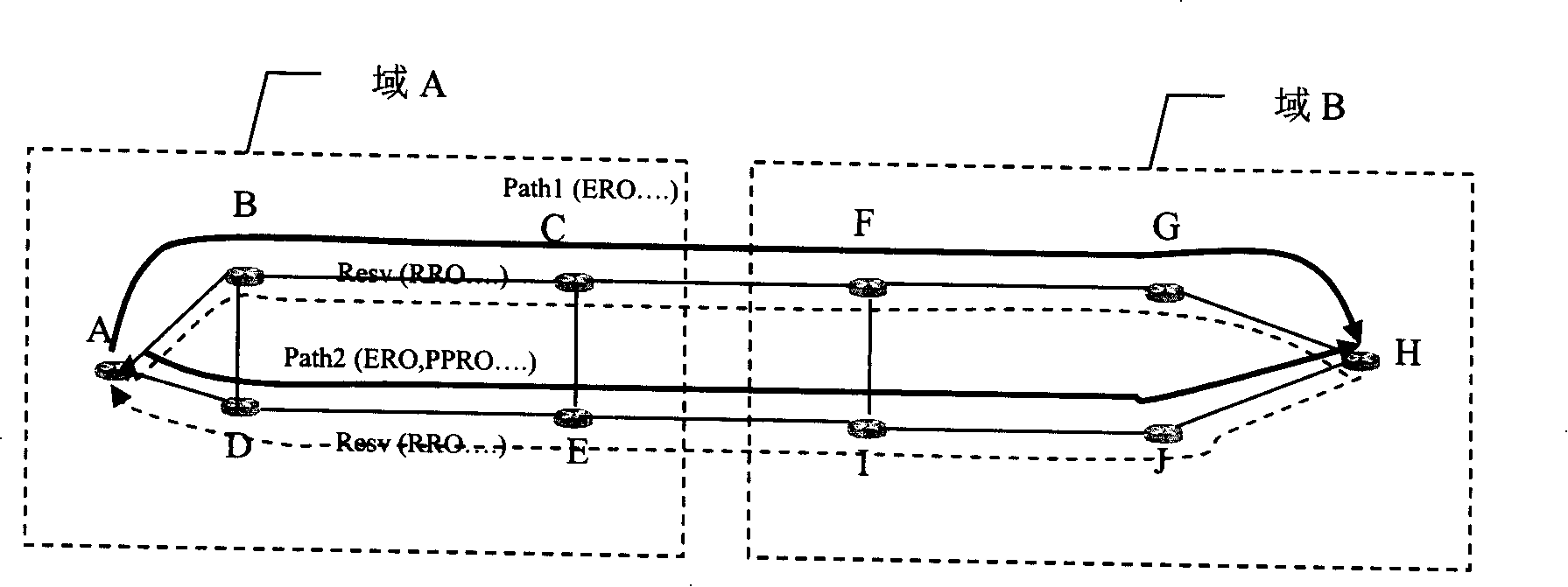
[0006] According to the above prior art, the inventor found in the process of the invention that based on the problem of cross-domain end-to-end path separation, the existing technical solutions cannot solve the following situation: in a multi-domain network, although different SRLG value, but because the allocation of SRLG is a management policy of a management domain, SRLG is not globally unique, so there may be different actual physical topologies with the same SRLG attribute, which will result in the calculated "separation" path and Separation of shared risk link groups for cross-domain paths cannot be achieved

Method used


Image

  • Method for implementing shared risk link circuit group separation crossing field path
  • Method for implementing shared risk link circuit group separation crossing field path
  • Method for implementing shared risk link circuit group separation crossing field path

Examples


Embodiment 1

[0046] Embodiment 1 of the present invention implements SRLG separation of cross-domain paths based on a PCS serial computing manner. The technical solution specifically includes the following steps.

[0047] S101. The network manager configures the SRLG association mapping table based on the network for the PCS corresponding to each domain in the network.

[0048] S102. The service source node initiates a cross-domain path calculation request for N (N is an integer greater than 1) SRLG separation from the source node to the destination node to the PCS of its domain (the first domain).

[0049] S103. After receiving the path calculation request, the PCS in the domain where the source node is located completes the path calculation in the domain, obtains the SRLG information used by the path at the same time, and then combines the calculated path segment information with the path calculation The request is also sent to the PCS of the next domain (the second domain), wherein the...

Embodiment 2

[0061] Embodiment 2 of the present invention implements SRLG separation of cross-domain paths based on a PCS parallel computing manner. The technical solution specifically includes the following steps.

[0062] S201. The network manager configures the SRLG association mapping table based on the network for the PCS corresponding to each domain in the network.

[0063] S202. The service source node initiates a cross-domain path calculation request for N (N is an integer greater than 1) SRLG separation from the source node to the destination node to the PCS of its domain (the first domain).

[0064] S203. After receiving the path calculation request, the PCS in the domain where the service source node is located calculates M1 (M1 and N are integers greater than 1, and M1 is not less than N) SRLG separated path sections in the domain, and obtains the path at the same time The SRLG information used by the section, and then send the calculated path section information together with...

Embodiment 3

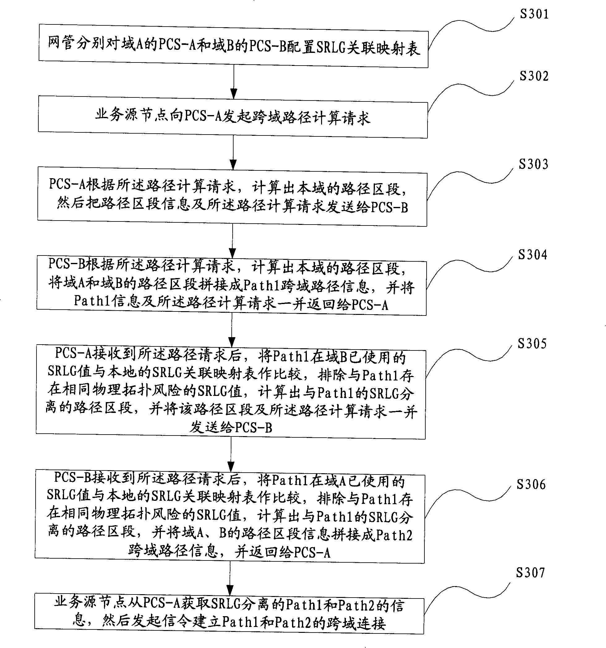
[0078] Such as image 3 as shown, image 3 It is a flow chart of implementing SRLG separation of cross-domain paths based on PCS serial computing in an embodiment of the present invention. The technical solution of Embodiment 3 of the present invention will be further elaborated below.

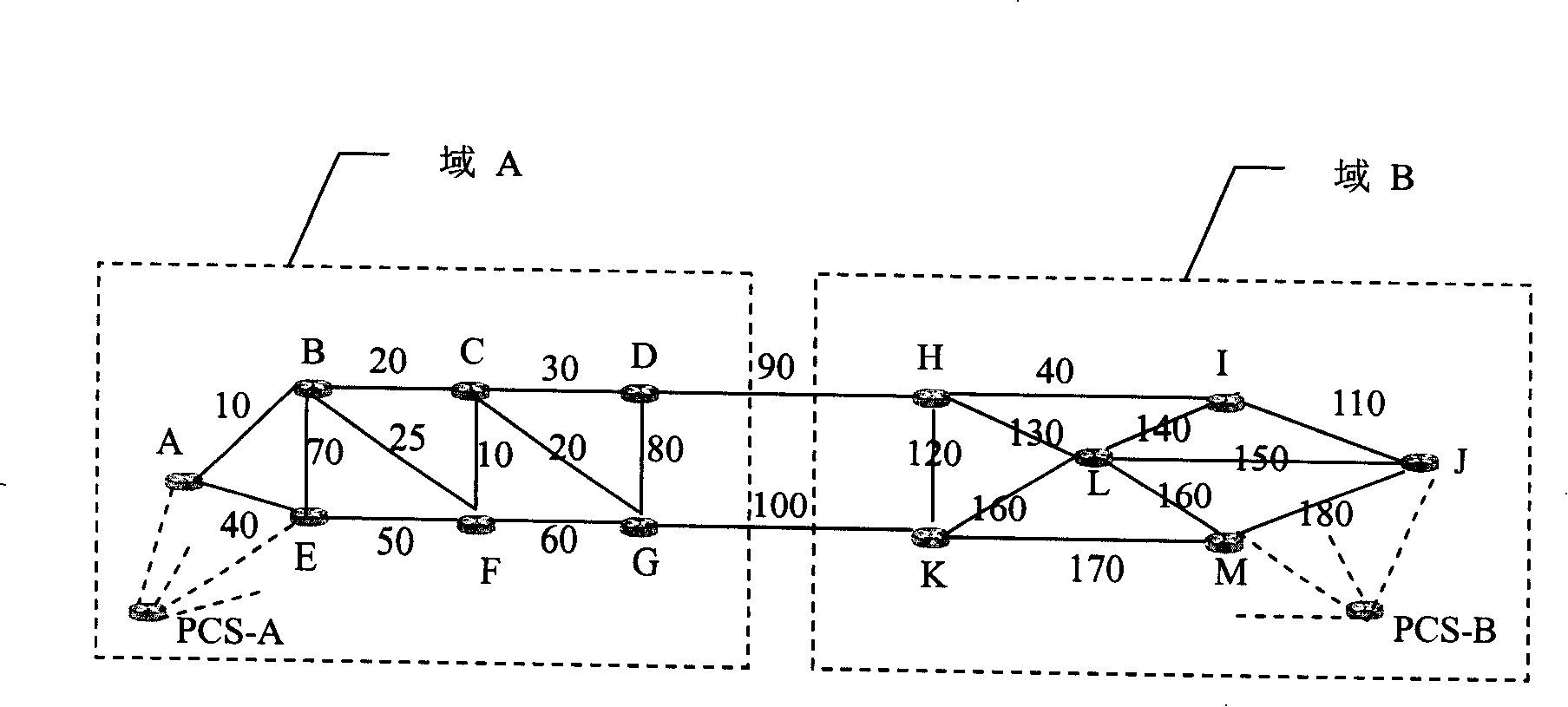
[0079] S301. The network management configures the SRLG association mapping table for the PCS-A of domain A and the PCS-B of domain B respectively, wherein the information of the SRLG association mapping table stored in PCS-A and PCS-B is as follows:

[0080] Table 2 is the SRLG association mapping table configured by the network management for PCS-A

[0081] associated domain

The SRLG value of the associated domain

Associated domain

The SRLG value of the associated domain

A

30

B

170

A

70

B

40

A

60

B

190

[0082] Table 3 is the SRLG association mapping table configured by the network...


PUM


Abstract

The implementing case of the invention relates to the technical field of network communication, which particularly discloses a method for separating a sharing risk link circuit group of an actual cross-domain path. The method comprises leading a traffic source node to launch cross-domain path calculating request which is separated by N sharing risk link circuit groups from the traffic source node to a traffic destination node, receiving the path calculating request by a path calculating server of each area where the cross-domain path needs to pass, calculating path sections which are separated by the cross-domain risk link groups of local area according to the information of association mapping table of the local sharing risk link circuit group, utilizing the path calculating server where traffic destination node is located to split the path sections which are calculated by the path calculating server of each area to be a complete N cross-domain paths, achieving the separation of the sharing risk link circuit group among N cross-domain paths, and N is an integer which is more than one. The SRLG separation of cross-domain paths is achieved through utilizing the above technical proposal, and the problem that the same physical topological risks existed among several cross-domain paths can be effectively avoided.

Description

technical field [0001] The invention relates to the technical field of network communication, in particular to a method for realizing the separation of shared risk link groups of cross-domain paths in the technical field of transmission network. Background technique [0002] Traditional optical networks, such as synchronous digital hierarchy (Synchronous Digital Hierarchy, SDH), synchronous optical network (Synchronous Optical Network, SONET) and optical transport network (Optical Transport Network, OTN), mainly adopt the form of self-healing ring networking, bandwidth utilization not tall. Moreover, traditional optical networks (SDH, SONET) are statically configured through network management, and mainly adopt ring networking, which is complex, time-consuming, and has low bandwidth utilization. With the demand for multi-service, high bandwidth, high survivability, and fast connection provision, the existing network architecture and networking methods will be impacted, and ...

Claims


Application Information

Patent Timeline
Patent Type & Authority Applications(China)
IPC IPC(8): H04L12/54H04L12/24H04L29/06H04L12/28H04L12/46H04L12/70
Inventor 章发太虞红芳赵太飞
Owner HUAWEI TECH CO LTD
Learn More