Sander delivering roller jack horse structure

A technology for conveying rollers and sanding machines, which is applied to roller tables, abrasive belt grinders, transportation and packaging, etc. It can solve the problems of reducing the rigidity of roller stands, being unable to adjust unilaterally, and reducing the accuracy of operation, so as to improve convenience and reliability, convenient adjustment of the amount of sanding, and the effect of small matching clearance

Active Publication Date: 2008-07-30
HANGZHOU XIANGSHENG ABRASIVE MACHINE MFG
View PDF0 Cites 8 Cited by
  • Summary
  • Abstract
  • Description
  • Claims
  • Application Information

AI Technical Summary

Problems solved by technology

[0002] In the structural design of the existing sanding machine conveying roller stand, one is that the fine-tuning between the lower idler roller and the sanding roller is realized by lifting the sanding roller spindle, and the sanding roller is a high-precision, For the main components of high-speed rotation, one more movable structure will inevitably produce a matching gap, thereby reducing the accuracy of operation and causing adverse effects on high-speed operation
Second, the mechanism can only lift both sides of the sanding roller synchronously, but cannot be adjusted unilaterally; third, the reduction box is located in the roller stand and is directly connected to the conveying roller shaft; fourth, the lower supporting rollers are fixed structures, and the sanding The distance between the smooth roller and the lower idler roller is realized by the overall lifting of the roller table and the adjustment of the sanding roller. The disadvantages are: first, the reduction box is located in the roller table, which not only makes the weight of the roller table heavy, but also Increase the width of the roller stand, thereby reducing the rigidity of the roller stand, as well as the rigidity of the lower frame and the sanding head; second, because the reduction box is located in the roller stand, not only the reliability is poor, but also the maintenance is inconvenient

Method used


Image

  • Sander delivering roller jack horse structure
  • Sander delivering roller jack horse structure

Examples


Embodiment 1

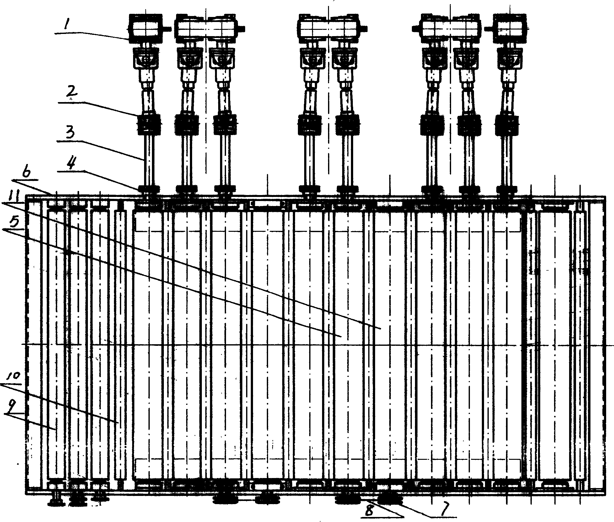
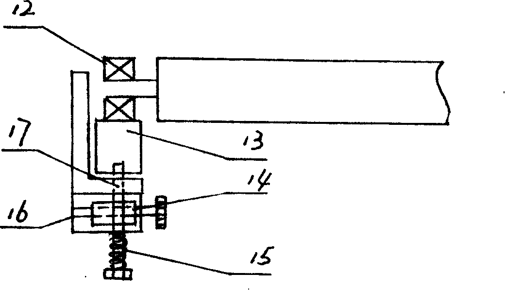
[0009] Embodiment 1: with reference to attached figure 1 and 2 . Sander conveying roller stand structure, 2 or more conveying rollers 5 are positioned on the shaft seats in the roller stand 6, the processing and manufacturing of conveying rollers 5 is the prior art, and will not be described here. Two or more conveying rollers 5 are respectively connected to the reduction box 1 located outside the roller stand through the conveying coupling shaft 3 and the universal joint 2 (one end of the two or more conveying rollers 5 adopts the conveying coupling flange 4 and the conveying One end of the coupling shaft 3 is connected, and the other end of the conveying coupling shaft 3 is connected to the output shaft of the reduction box 1 through the universal joint 2. One or two or more lower idlers 11 are respectively distributed between the multiple conveying rollers 5 and Through the transmission mechanism (sprocket, chain transmission mechanism), the conveyor roller 5 drives the l...


PUM


Abstract

The invention relates to a transporting roll platform structure of roll wheel transportation sanding machine. Two or a plurality of transporting rolls are positioned on an axial seat in a roll platform frame; one end of the two or the plurality of transporting roll are respectively connected with a reduction gearbox located outside the roll platform frame through a transporting shaft and a universal joint; one roll or two or a plurality of lower support rolls are respectively distributed among a plurality of transporting rolls and the lower support rolls are driven by the transporting rolls through a transmission mechanism. The invention has the advantages that: first, the lower support roll adopts the adjustable structure and is designed into the structure with one side adjustable or two sides adjustable, which greatly facilitates the adjustment of sand cutting capacity at the two sides in grinding and overcomes the defects in background technology; second, a cross drive transporting rolls formed by the transporting shaft and the universal joint is used for minimizing a tolerance clearance; third, the reduction gearbox is positioned outside the roll platform frame, thus narrow the roll platform frame, lightening the weight as well as improving rigidity of the roll platform frame, a machine frame and a sanding joint; fourth, convenience and reliability of maintenance are greatly improved.

Description

technical field [0001] The invention relates to a conveying roller table structure of a roller conveying sander, which belongs to the field of sander component assembly manufacturing. Background technique [0002] In the structural design of the existing sanding machine conveying roller stand, one is that the fine-tuning between the lower idler roller and the sanding roller is realized by lifting the sanding roller spindle, and the sanding roller is a high-precision, For the main components of high-speed rotation, one more movable structure will inevitably produce a matching gap, thereby reducing the accuracy of operation and causing adverse effects on high-speed operation. Second, the mechanism can only lift both sides of the sanding roller synchronously, but cannot be adjusted unilaterally; third, the reduction box is located in the roller stand and is directly connected to the conveying roller shaft; fourth, the lower supporting rollers are fixed structures, and the sandi...

Claims


Application Information

Patent Timeline
Patent Type & Authority Applications(China)
IPC IPC(8): B24B21/18B65G13/02
Inventor 陈勇奇
Owner HANGZHOU XIANGSHENG ABRASIVE MACHINE MFG
Why Eureka
Try Eureka