Moving device

A motion device and fluid technology, applied in the field of atmospheric aircraft, can solve problems such as difficult operation and control, complex structure, and unimproved airflow resistance of the fuselage and wings

Active Publication Date: 2008-07-30
朱晓义
View PDF1 Cites 18 Cited by
  • Summary
  • Abstract
  • Description
  • Claims
  • Application Information

AI Technical Summary

Problems solved by technology

Although this kind of inflatable wing can adjust the shape and angle of the wing according to the flight needs, its structure is complicated, the

Method used


Image

  • Moving device
  • Moving device
  • Moving device

Examples


Embodiment 1

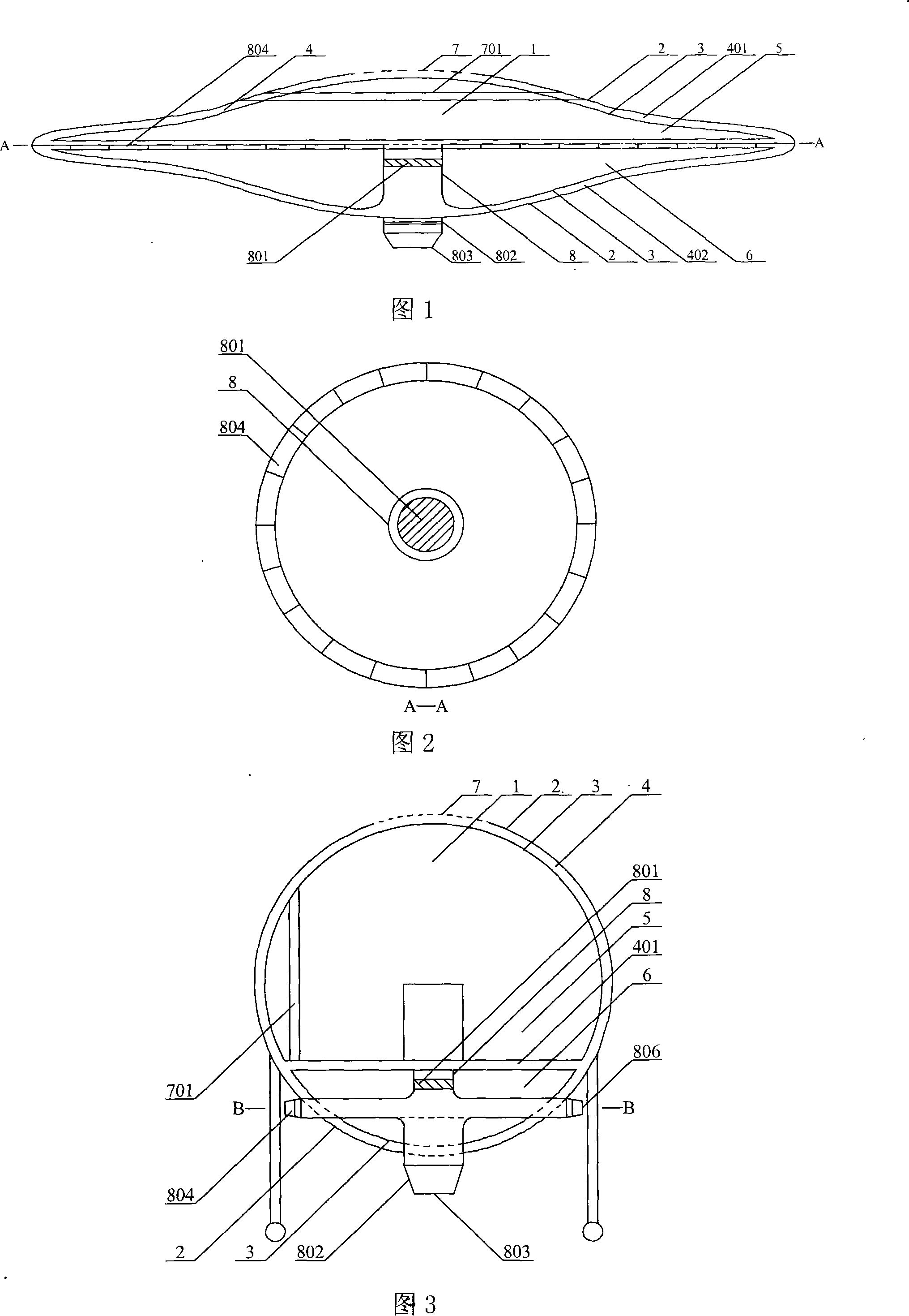
[0055] A kind of flying saucer, as shown in Figure 1 and Figure 2, the overall shape of the flying saucer body 1 is a flying saucer shape, the outer layer of the shell includes an outer shell 2 and an inner shell 3, and there is a certain distance between the inner shell 3 and the outer shell 2. Internal fluid passage 4.

[0056] The internal fluid passage 4 has a fluid suction port, which is opened on the first side, and includes a forward suction port 7 and a side suction port 701 . The forward suction port 7 is located on the top surface of the flying saucer; the lateral suction port 701 comprises a plurality of openings on the upper casing 2, and the first flow regulator is provided in the side suction port 701, and the first flow regulator is similar to The annular window of the louver can communicate the external fluid space with the internal fluid passage 4, and its air intake angle can be adjusted. The side suction port 701 can be a closed ring around the casing, or a...

Embodiment 2

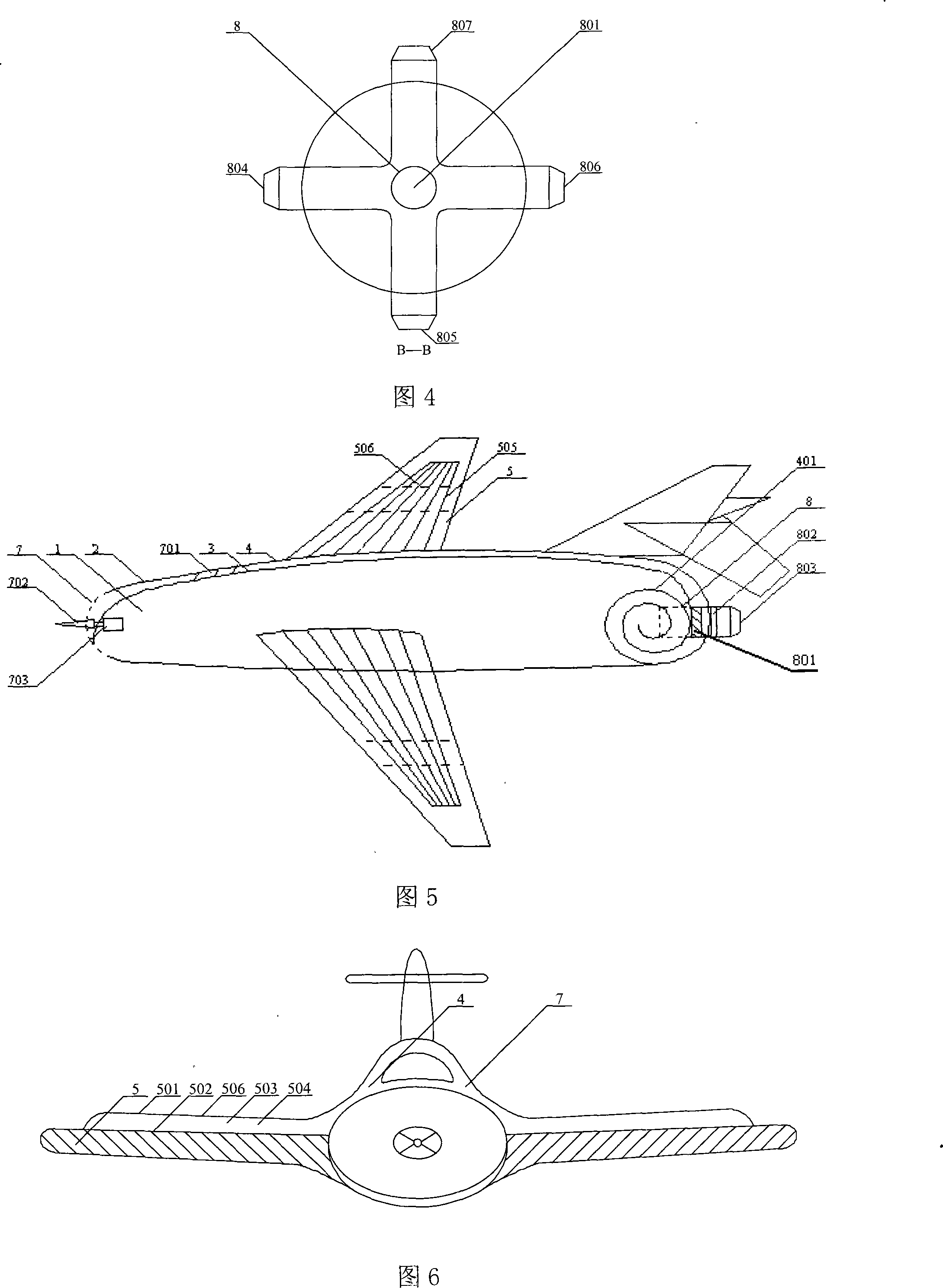
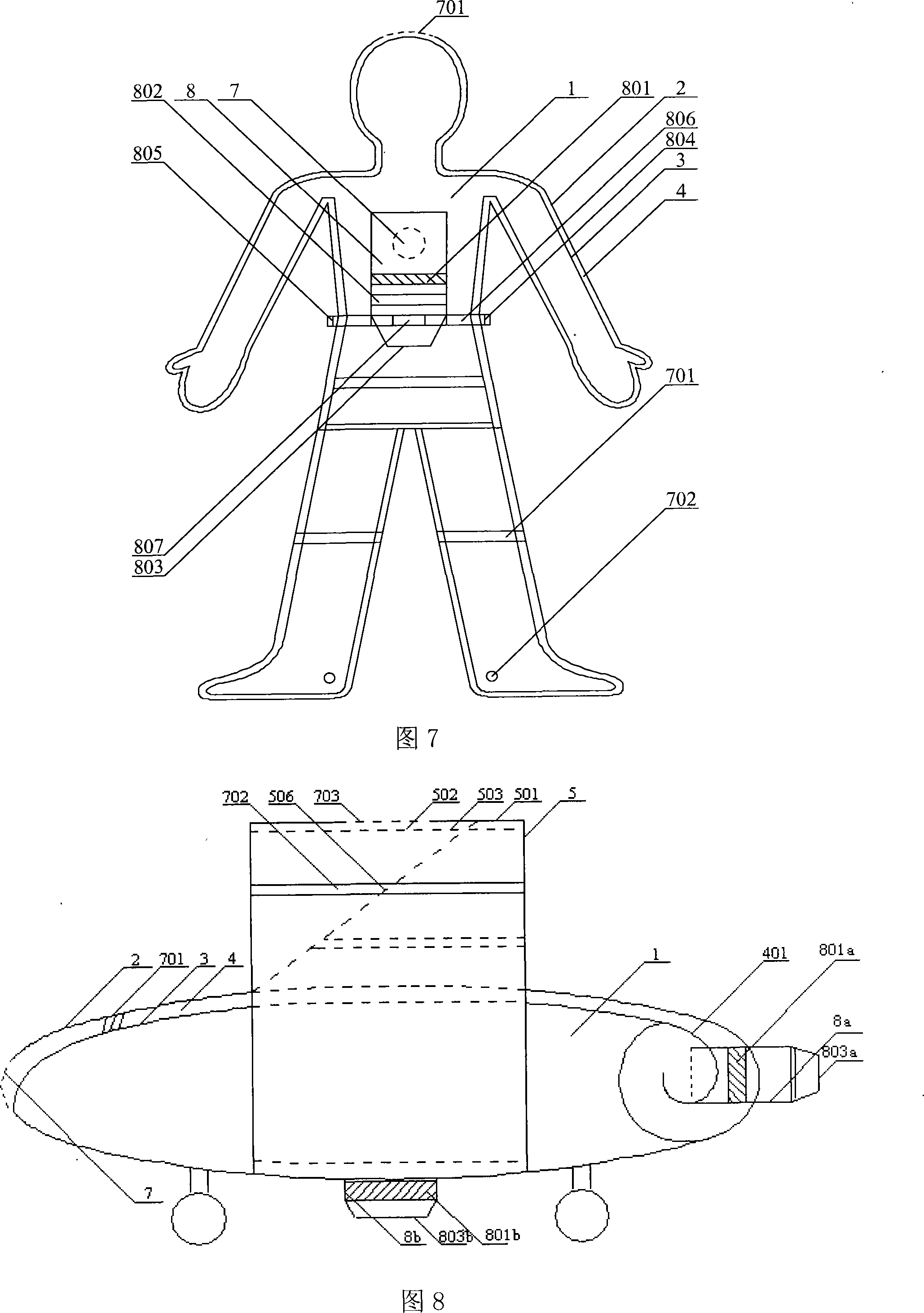
[0062] A spherical aircraft, as shown in Fig. 3 and Fig. 4, differs from Embodiment 1 in that: the aircraft is spherical as a whole; the inner space of the inner shell is divided into an upper semicircle 5 and a lower semicircle 6, and the fluid layer between them The channel 401 communicates with the internal fluid channel 4; the fluid ejection port includes a first fluid ejection port and a second fluid ejection port, wherein the second ejection port is located on the lower semicircle 6, and includes ejection ports facing four directions respectively: the fluid ejection port 804 , fluid ejection port 805, fluid ejection port 806, fluid ejection port 807, each fluid ejection port caliber air outlet end surface can be enlarged, reduced, closed and opened, when necessary, other fluid ejection ports can be closed, and the required fluid ejection port can be opened exhaust. The front end of the fluid ejection port 803 is provided with a second flow regulator, and the second flow ...

Embodiment 3

[0066] An aircraft, as shown in Figure 5 and Figure 6, has the following differences from Embodiment 1.

[0067] The inner fluid channel 4 forms a spiral fluid layer 401 at the rear shell 2 and the inner shell 3 , and the spiral fluid layer 401 can increase the passage of the upper fluid of the fuselage. The fluid ejection port 803 is installed on the end face of the exhaust channel 8 and communicates with the spiral fluid layer 401 , and its ejection port can be enlarged or reduced by adjusting the movable sleeve 802 . A jet engine 801 is fixed inside the outlet cylinder 8 . The internal channel 4 on the entire fuselage and the two layers of high-speed fluid layers on the outer shell 2 are independent and connected to each other, and under the strong suction of the jet engine 801, the fluid flow speed close to the outer shell 2 is faster than the movement of the aircraft The speed, at this time, is such that the various fluid drags approximately equal to the speed of motion ...


PUM


Abstract

The invention discloses a movement device, which comprises a shell and is characterized in that an internal liquid channel and a negative pressure generator are further included, wherein, a first side of the shell is provided with at least a liquid suction inlet; a second side of the shell is provided with at least a liquid spraying outlet; the inside of the shell is provided with the internal liquid channel communicated with the liquid suction inlet and the liquid spraying outlet; the inside of the internal liquid channel is provided with a negative pressure generator; when the negative pressure generator works, outside liquid is sucked by the liquid suction inlet and flows through the internal liquid channel, and then the liquid is sprayed out from the liquid spraying outlet. The invention arranges the internal liquid channel inside the shell, so as to lead the liquid from a front end, a top and sides during movement into the channel and lead the liquid resistance to a place requiring to generate push force and spray the liquid from the liquid spraying outlet, thus generating push force and changes the resistance into power. In addition, the internal liquid channel is long, so the lift force of the movement device can be increased.

Description

technical field [0001] The invention relates to a movement device, in particular to an airplane, a flying saucer, an automobile, a train, a submarine, a boat, and especially to an atmospheric aircraft. Background technique [0002] Since the birth of the aircraft, the upper surface of the wing has an arc shape and the lower surface has a planar shape. The upper and lower surfaces of the wing generate a pressure difference in the high-speed airflow, that is, generate lift. According to this principle of lift force, there have been no fundamental changes and breakthroughs in the wings of airplanes in the past century. Simultaneously owing to use fixed wing, fixed engine structure, the maneuverability of the control of aircraft is poor, there is stall phenomenon, can't control the airflow around fuselage. The feathers of a bird's wing are one layer of feathers covering the next layer of feathers. From the front of the wing to the body of the bird, the feathers are opened when ...

Claims


Application Information

Patent Timeline
IPC IPC(8): B62D37/02B63B1/32B64C23/00F15D1/02
CPCY02T70/12Y02T70/10
Inventor 朱晓义
Owner 朱晓义
Why Eureka
Try Eureka