
Annular bearing bottom plate grillage beam type wind-power generating tower foundation

An annular and basic technology, applied in the foundation field of the annular pressure-bearing floor well lattice beam wind power tower, can solve the problems of long overhang, waste of foundation design, uneconomical foundation, etc.

Inactive Publication Date: 2008-07-30
TONGJI UNIV
View PDF1 Cites 15 Cited by
  • Summary
  • Abstract
  • Description
  • Claims
  • Application Information

AI Technical Summary

Problems solved by technology

However, for wind power towers, the main force of the superstructure on the foundation is not the pressure but the bending moment. Therefore, the traditional independent expansion foundation has more than enough compression resistance and insufficient bending resistance, thus causing a large waste of foundation design.
[0003] The existing independent expansion foundation of wind power tower mostly adopts variable thickness cantilever slab as the foundation floor. Due to the large size of the foundation plane, the length of the slab cantilever is large, and the structural effect of the cantilever slab is very large, so the foundation is uneconomical and the investment bigger

Method used


Image

  • Annular bearing bottom plate grillage beam type wind-power generating tower foundation
  • Annular bearing bottom plate grillage beam type wind-power generating tower foundation

Examples


Embodiment Construction

[0017] The present invention will be further described below in conjunction with accompanying drawing.

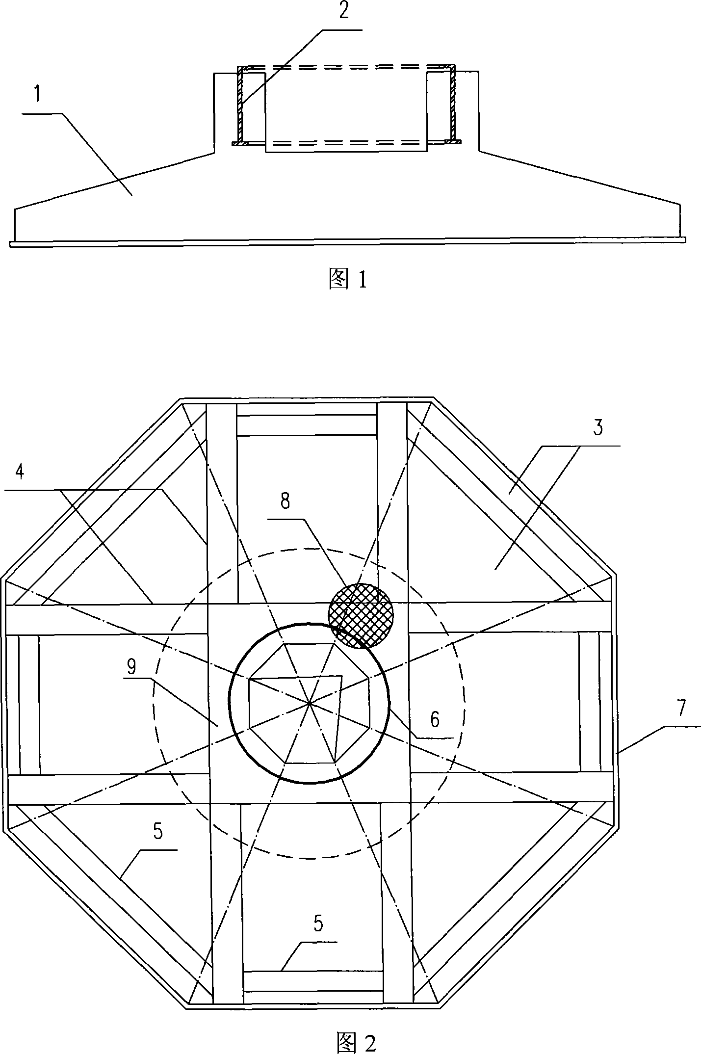
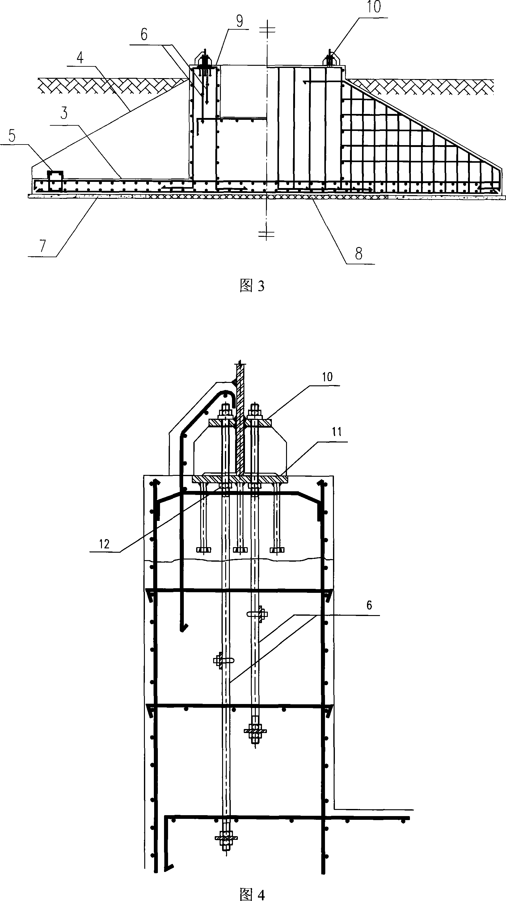
[0018] As shown in Figures 2, 3, and 4, the foundation form mainly includes annular pressure-bearing foundation floor 3, cantilever beam 4, edge beam 5, prestressed pre-embedded anchor bolt 6, annular concrete cushion 7, expanded polystyrene Plate backing plate 8. Wherein, the concrete cushion layer 7 is in the form of a ring, and an expanded polystyrene plate backing plate 8 is embedded in its center, and a concrete base plate 3 and a concrete base plate 3 are arranged above the cushion layer 7 and the expanded polystyrene plate plate 8 A concrete foundation center tube 9 is arranged above the middle part, and the cantilever beam 4 protrudes outward from the concrete foundation center tube 9, and the two ends of the edge beams 5 are connected to the cantilever beam 4 to form a well-shaped structure; Anchor bolts 6 are evenly buried, and the number of anchor bolts 6 is 200...


PUM


Abstract

The invention relates to a ring-shaped pressure bearing bottom plate checker-shaped beam type wind power generation tower foundation which consists of a concrete foundation slab, a socle beam, an edge trabecula, prestress cast-in fixing bolts, a concrete cushion, a soft backing plate and a concrete foundation center tube; the center of the ring-shaped concrete cushion is embedded with the soft backing plate, the concrete foundation slab is arranged on the concrete cushion and the soft backing plate, the concrete foundation center tube is arranged above the middle part of the concrete foundation slab, the socle beam extends from the concrete foundation center tube, both ends of the edge trabecula are connected with the socle beam so as to form a checker-shaped structure; the tube wall of the concrete foundation center tube is evenly buried with fixing bolts, all the fixing bolts form a fixing bolt group, the top of the fixing bolts is provided with a fixing bolt top slab; an adjusting screw nut is positioned below the fixing bolt top slab, and the top surface of the adjusting screw nut is on the same level with the top of the tub wall of the concrete foundation center tube. In the invention, the prestress cast-in fixing bolt style is adopted for connecting steel power feet of a wind power generation tower with the foundation; thereby the invention can ensure the rigid connection between a tower drum and the foundation, reduce the steel consumption of the part of the steel tower drum buried into the foundation, and simplify the construction of the part at the same time.

Description

technical field [0001] The invention relates to a foundation structure of a wind power generation tower, in particular to an annular pressure-bearing floor well grid beam type wind power generation tower foundation. Background technique [0002] At present, the foundation of wind power towers on medium-hard foundation soil mostly adopts independent expansion foundation, and its structure is shown in Figure 1. The combination of independent expansion foundation and appropriate foundation conditions can achieve better compressive bearing capacity, so it is often used in building column foundations. But for wind power towers, the main force of the superstructure on the foundation is not the pressure but the bending moment. Therefore, the traditional independent expansion foundation has more than enough compression resistance and insufficient bending resistance, thus causing a large waste of foundation design. [0003] The existing independent expansion foundation of wind power...

Claims


Application Information

Patent Timeline
Patent Type & Authority Applications(China)
IPC IPC(8): E02D27/42
Inventor 马人乐
Owner TONGJI UNIV
Learn More