Electromagnetic lock

An electromagnetic lock and electromagnetic coil technology, applied in the field of electromagnetic locks, can solve problems such as large installation space, and achieve the effects of good safety, wide adaptability, and small installation volume

Inactive Publication Date: 2008-07-30
GUANGZHOU JIJIA INFORMATION TECH
View PDF1 Cites 11 Cited by
  • Summary
  • Abstract
  • Description
  • Claims
  • Application Information

AI Technical Summary

Problems solved by technology

When installing this kind of electromagnetic lock, both ends of the lock tongue and the lock card need a large installation space.

Method used


Image

  • Electromagnetic lock
  • Electromagnetic lock
  • Electromagnetic lock

Examples


Embodiment Construction

[0019] The present invention will be further described in detail below in conjunction with the embodiments and the accompanying drawings, but the embodiments of the present invention are not limited thereto.

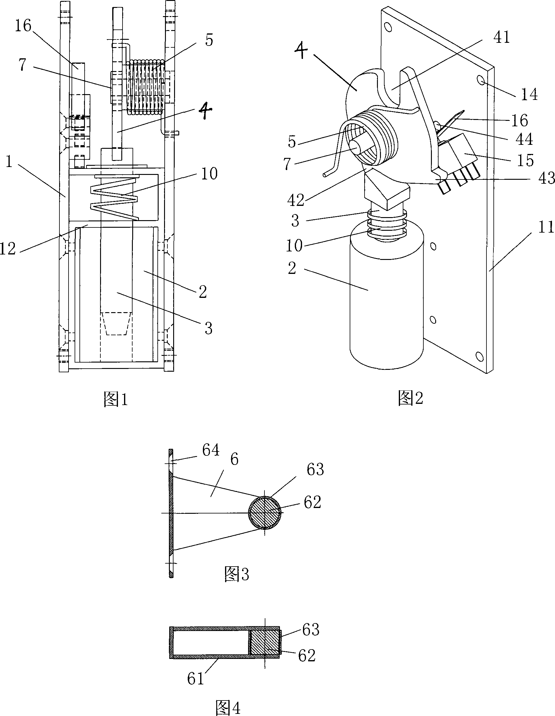
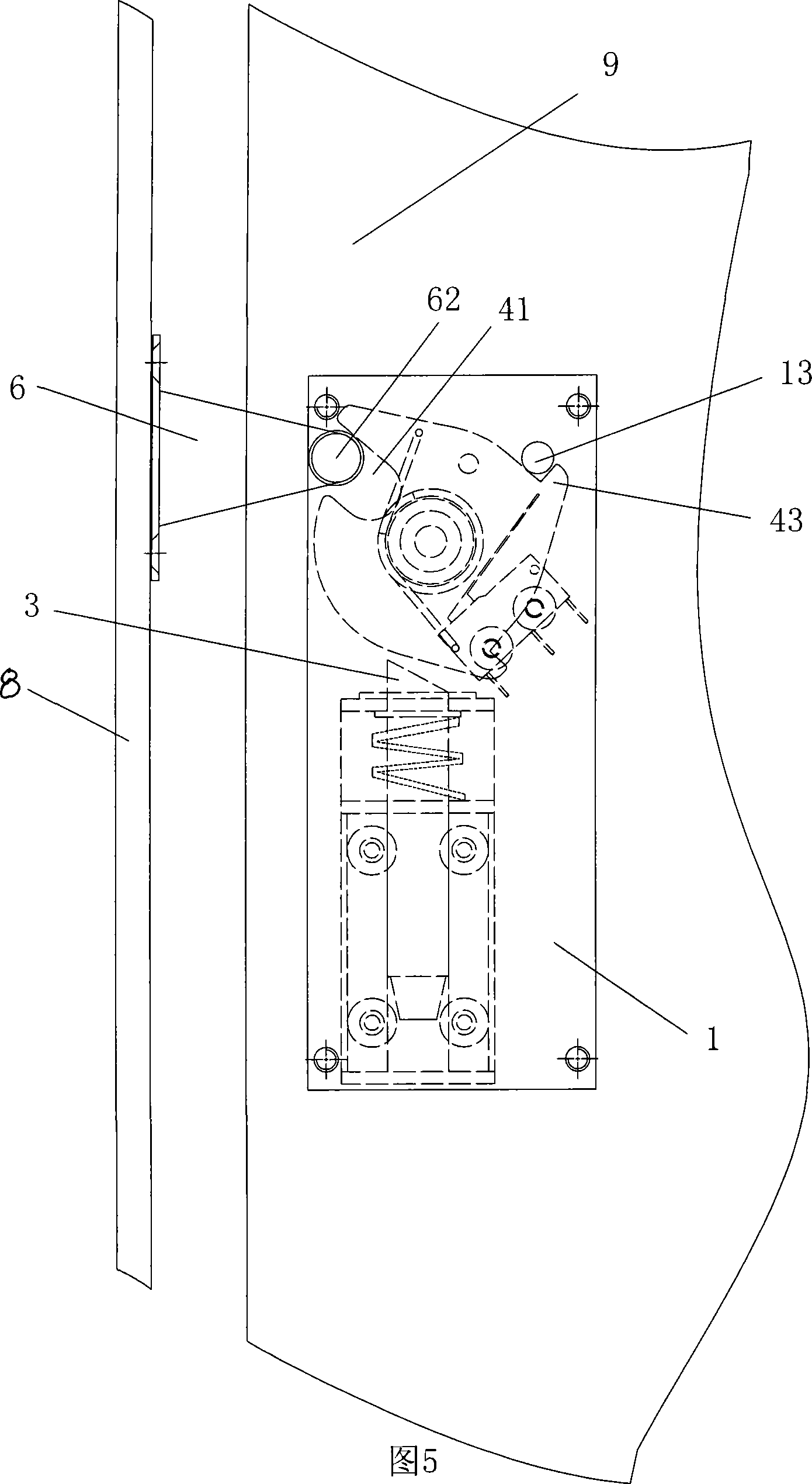
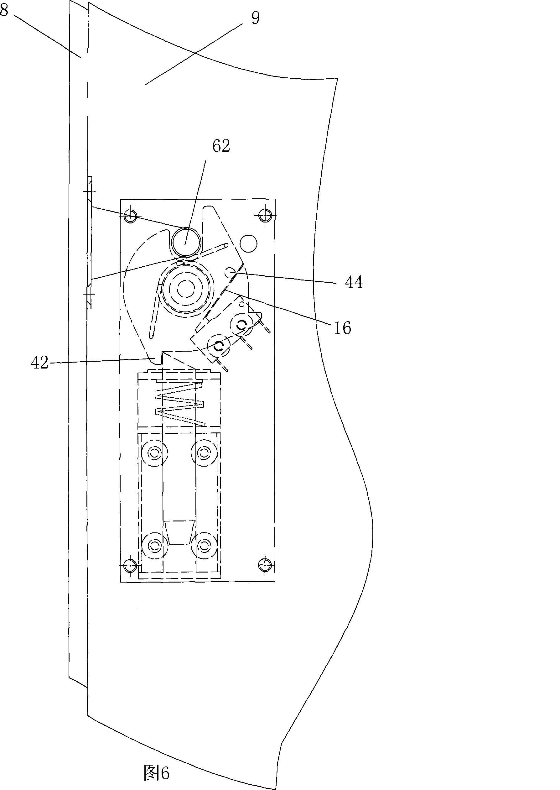
[0020] As shown in Figure 1, electromagnetic lock of the present invention is made up of lock frame 1, electromagnetic coil 2, conductive iron core 3, dead bolt 4, dead bolt return spring 5, lock card 6 (see Fig. 3) etc. The lock frame 1 is made up of two flat plates 11 parallel to each other and a supporting frame 12 fixed between the two flat plates 11 , and the flat plates 11 have installation holes 14 . The electromagnetic coil 2 is fixed in the supporting frame 12, the conductive iron core 3 is located in the electromagnetic coil 2, and its upper end stretches out of the electromagnetic coil 2, and the upper end of the conductive iron core 3 is an inclined plane. The dead bolt 4 is sheet-shaped, with a locking groove 41, a locking projection 42 and a positioning pro...


PUM


Abstract

The invention discloses an electromagnetic lock which comprises a lock frame, an electromagnetic coil, a magnetic conductive iron core with an iron core reset spring, a lock tongue and a lock clasp. The lock tongue is in a sheet shape and is provided with a lock clasping groove which is used for locking the lock clasp, a locking lug which is used for locking the magnetic conductive iron core, and a positioning lug which is used for limiting the return travel of the lock tongue. The lock tongue is arranged at one end of the magnetic conductive iron core by a cantilever which is vertical to a sheet plane of the lock tongue, the locking lug is locked with one end of the magnetic conductive iron core, and the lock clasping groove is arranged oppositely to the lock clasp. An outer sleeve of the cantilever is provided with an offsetting spring for the lock tongue. One end of the offsetting spring for the lock tongue is connected with the lock tongue, and the other end is connected with the lock frame. The electromagnetic lock of the invention has the advantages of small volume of the whole lock, small installation space, simple and firm structure, favorable safety and wide suitability.

Description

technical field [0001] The present invention relates to electromagnetic locks, especially electromagnetic locks for electronic lockers. Background technique [0002] There are various electromagnetic locks on the market, most of which are complex in structure and large in size. The Chinese utility model patent with the patent number ZL93244393.1 discloses an electromagnetic lock head. The lock tongue is a conductive core set in the electromagnetic lock body. The lock tongue is provided with a positioning spring that can reset the lock tongue and a limit lock The positioning clip spring for the tongue displacement distance, the tail of the lock tongue is set in the electromagnetic coil, the rear end of the electromagnetic lock body is provided with a magnetic cover, and the lock card is provided with a groove that can cooperate with the front end of the lock tongue. When this electromagnetic lock is installed, both ends of the dead bolt and the lock card need a larger instal...

Claims


Application Information

Patent Timeline
Patent Type & Authority Applications(China)
IPC IPC(8): E05B47/06
Inventor 洪涛
Owner GUANGZHOU JIJIA INFORMATION TECH
Why Eureka
Try Eureka