Rotary type compressor and refrigeration circulating device having the same

A technology of rotary compressor and compression mechanism, applied in rotary piston machinery, rotary piston/oscillating piston pump components, and elastic fluid rotary piston/oscillating piston pump combinations, etc. Considering the problem of the rotating body assembly, the vibration cannot be sufficiently reduced, and the effect of excellent vibration resistance is achieved

Inactive Publication Date: 2008-07-30
TOSHIBA CARRIER CORP
View PDF2 Cites 8 Cited by
  • Summary
  • Abstract
  • Description
  • Claims
  • Application Information

AI Technical Summary

Problems solved by technology

[0006] However, the rotary compressor described in Patent Document 2 does not consider the position of the center of gravity of the rotating body assembly (Japanese: full-turning body) composed of the rotor, shaft, and roller, and cannot sufficiently reduce vibration.

Method used


Image

  • Rotary type compressor and refrigeration circulating device having the same

Examples


Embodiment Construction

[0044] Hereinafter, a rotary compressor and a refrigeration cycle apparatus having the rotary compressor according to an embodiment of the present invention will be described with reference to the drawings.

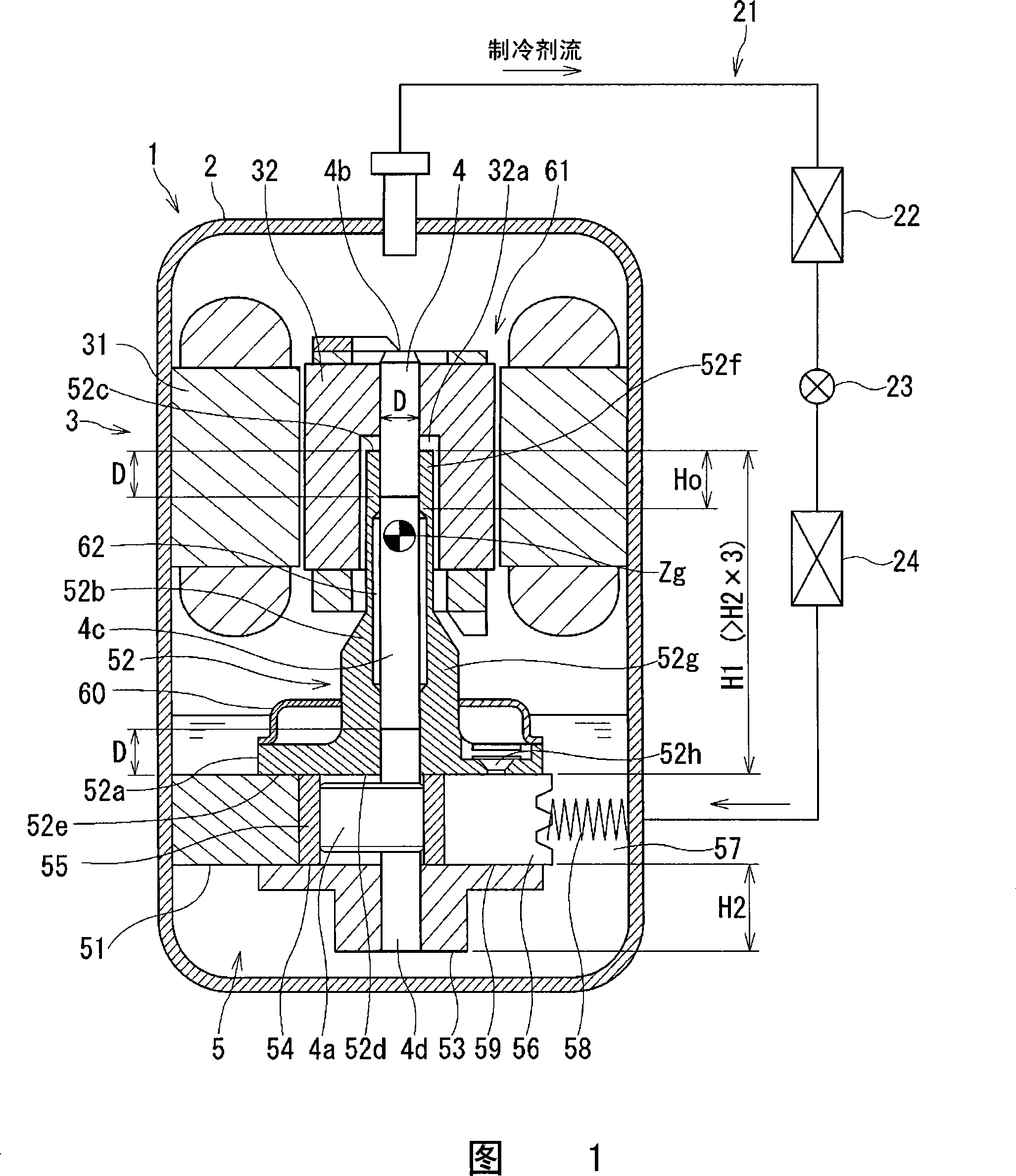
[0045] FIG. 1 is a schematic diagram of a rotary compressor and a refrigeration cycle device having the rotary compressor according to an embodiment of the present invention.

[0046] As shown in FIG. 1 , in the refrigeration cycle device 21 of the present invention, the rotary compressor 1 , condenser 22 , expansion device 23 and evaporator 24 of this embodiment are connected in a ring shape with pipes.

[0047] The rotary compressor 1 has an airtight container 2 , and includes a motor unit 3 accommodated in the airtight container 2 , and a compression mechanism unit 5 connected to the motor unit 3 via a rotating shaft 4 .

[0048] The motor part 3 includes: a stator 31 pressed into the airtight container 2, and a rotor 32 rotatably arranged on the inner periphery of the...


PUM


Abstract

The invention provides a rotary compressor with remarkable vibration resistance and a cooling circulation device with remarkable vibration resistance. In the rotary compressor, a bearing part, which axially supports a rotary axis fixedly connected with a rotor of an electromotor part, is only provided at the side of a compression mechanism part of the electromotor part, axial direction position of barycentre of a rotary object assembly composed by the rotor, the rotary axis and a roller, is located within the range over the distance equivalent to diameter of a main axis part of the rotary axis when leaving inwards from two ends of a main bearing. The cooling circulation device includes the rotary compressor with above structure.

Description

technical field [0001] The present invention relates to a rotary compressor and a refrigeration cycle apparatus (refrigeration cycle apparatus) provided with the rotary compressor, and more particularly to a rotary compressor in which a bearing member for axially supporting a rotating shaft is provided only on the side of the compression mechanism part of the motor part. Machines and refrigeration cycle installations with rotary compressors. Background technique [0002] Conventional rotary compressors generally have a one-sided support structure in which a bearing member for axially supporting the rotating shaft is provided only on the compression mechanism side of the motor unit, and thus has a problem that vibration is likely to occur. [0003] Therefore, Japanese Patent Laid-Open No. 2001-323886 (hereinafter referred to as Patent Document 1) proposes a rotary type with a double-sided support structure in which a bearing member is also provided on the side opposite to the...

Claims


Application Information

Patent Timeline
IPC IPC(8): F04C29/00F04C18/356
CPCF04C18/356F04C23/008F04C29/0021F04C2210/26F04C2240/40Y10S415/00Y10S417/902
Inventor 知念武士平山卓也
Owner TOSHIBA CARRIER CORP
Why Eureka
Try Eureka