Jam eliminating method of visible light communication system

A technology of visible light communication and optical system, which is applied in the field of eliminating ambient light interference and can solve problems such as seldom considering the influence of ambient light.

Inactive Publication Date: 2008-07-30
EAST CHINA UNIV OF SCI & TECH
View PDF0 Cites 42 Cited by
  • Summary
  • Abstract
  • Description
  • Claims
  • Application Information

AI Technical Summary

Problems solved by technology

However, the usual research only considers the influence of...

Method used


Image

  • Jam eliminating method of visible light communication system
  • Jam eliminating method of visible light communication system
  • Jam eliminating method of visible light communication system

Examples


Embodiment Construction

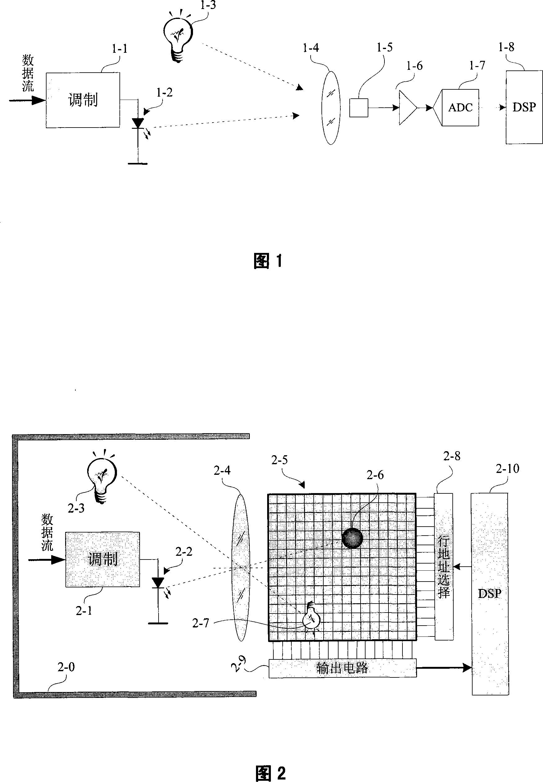
[0033] A conventional optical communication system consists of an optical transmitting end and an optical receiving end. As shown in Figure 1, the data stream to be sent is modulated by a modulator (1-1), and the communication light source (1-2) is driven to send the modulated signal carrying data information. pulsed light. Communication light sources are typically light emitting diodes (infrared, laser or visible light). At the receiver end, the optical signal in the field of view is converged on the photoelectric converter (1-5) through the optical system (1-4), and the optical system generally includes a filter for filtering out-of-band stray light. Photoelectric converters for communication applications are generally unitary, and multi-element converters are mainly used in imaging or positioning systems. The output of the photoelectric converter is generally filtered, amplified (1-6), and converted from analog to digital (1-7), and then sent to a digital signal processor ...


PUM


Abstract

The invention proposes an interference cancellation method of a visible light communication system. The visible light communication is most vulnerable to be interfered by the environmental light, the invention adopts an optical space division method to separate an interference source and a communication light source on a photoelectric sensor, then a background interference value is obtained by using the time-related sampling and the space-related sampling, after that, the background interference value is subtracted from the output of the data signal according to the function weight, so as to offset the impact of the background light.

Description

technical field [0001] The invention belongs to the field of optical wireless communication, in particular to a method for eliminating ambient light interference in an optical receiver. Background technique [0002] The receiver of the optical communication system is mainly composed of an optical system, a photodetector and a signal processing circuit. The optical system collects and filters the optical signals in the space and makes them converge on the photodetector; the photodetector converts the optical signal into an electrical signal and outputs it to the signal processing circuit; the signal processing circuit performs corresponding amplification, filtering, detection, demodulation, Decoding and other final output data. [0003] Optical fiber communication is one of the main optical communication technologies and belongs to wired communication. Optical fiber communication uses laser light as the emission light source. During the entire transmission process, the chan...

Claims


Application Information

Patent Timeline
IPC IPC(8): H04B10/10H04B10/116
Inventor 樊凌涛
Owner EAST CHINA UNIV OF SCI & TECH
Why Eureka
Try Eureka