Drive device

A driving device and casing technology, applied in magnetic drive clutches, non-mechanical drive clutches, transportation and packaging, etc., can solve problems such as sensor short-circuit faults and short-circuit faults, and achieve the effect of preventing short-circuit faults

Inactive Publication Date: 2008-07-30
AISIN SEIKI KK +1
View PDF2 Cites 4 Cited by
  • Summary
  • Abstract
  • Description
  • Claims
  • Application Information

AI Technical Summary

Problems solved by technology

[0004] However, if the wear powder generated along with the operation of the electromagnetic clutch mechanism is scattered toward the circuit board including the sensor, it may cause a short-circuit failure of the sensor.
In addition, for example, when adopting a structure in which the electronic control unit is housed integrally in the casing, it may also cause a short-circuit failure of the electronic control unit on which important and delicate components such as a microcomputer are mounted.

Method used


Image

  • Drive device
  • Drive device
  • Drive device

Examples


Embodiment Construction

[0020] Hereinafter, an embodiment embodying the present invention will be described based on the drawings.

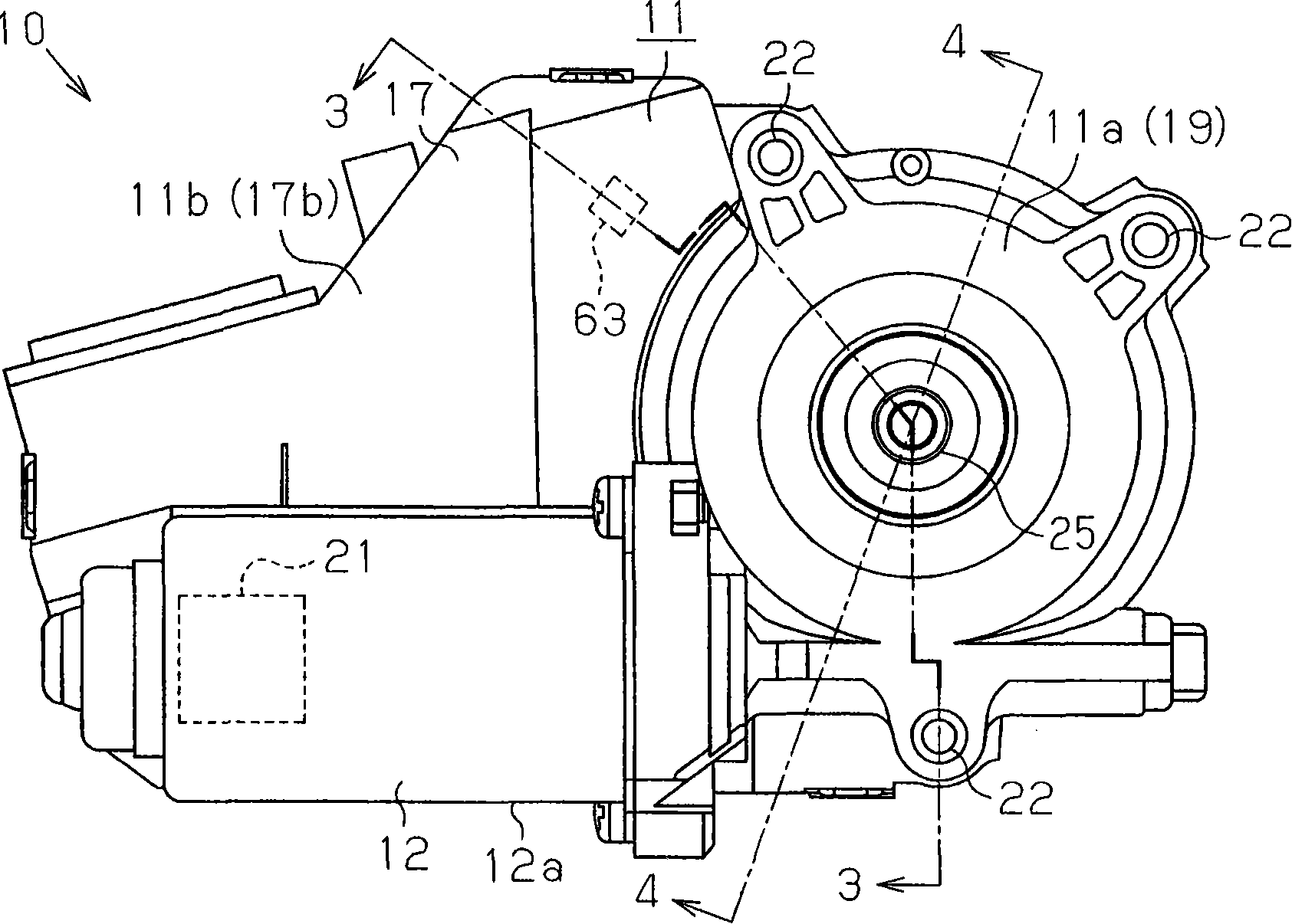
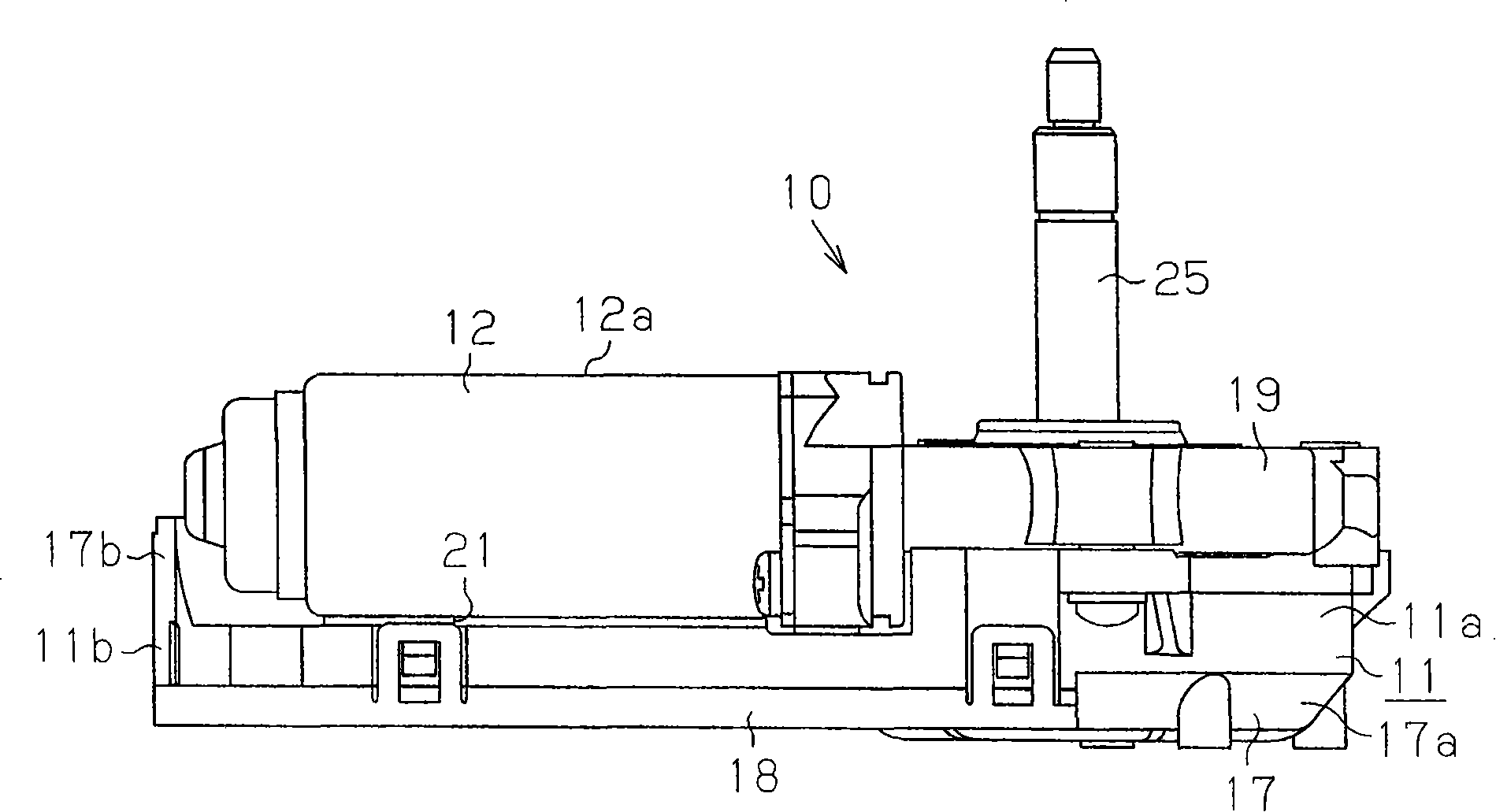
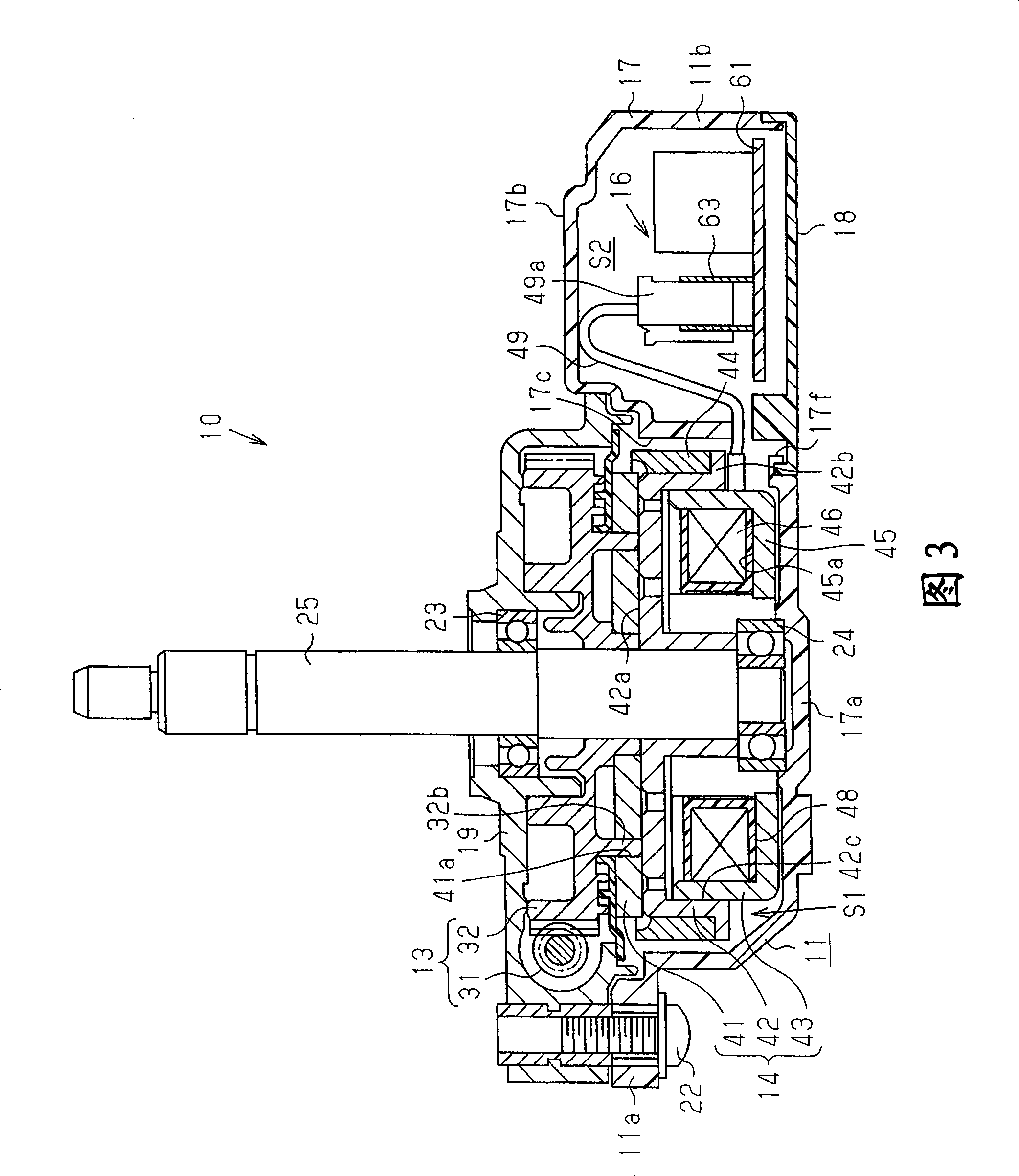
[0021] like figure 1 4, the driving device 10 includes: a casing 11, a motor 12, a reduction mechanism 13, a friction electromagnetic clutch mechanism 14, a sensor 15, and an electronic control unit (hereinafter referred to as "ECU") 16 as a control device. . The reduction mechanism 13 and the electromagnetic clutch mechanism 14 constitute a drive transmission mechanism section. The casing 11 includes a housing 17 , an ECU cover 18 , and a motor casing 19 .

[0022] The above-mentioned case 17 is made of a resin material, and has an integral first case part 17a and a second case part 17b. The first case portion 17a and the second case portion 17b are opened in opposite directions, that is, openings are formed facing upward and downward in FIG. 3 , so that the case 17 has an approximately S-shaped cross section. A partition wall 17c extending in the axial direction o...


PUM


Abstract

The present invention provides a drive device comprising a casing (11) and an electromagnetic clutch mechanism (14) housed in the casing. The electromagnetic clutch mechanism (14) has an armature (41) freely rotatably supported on the casing (11), and a rotor (42) disposed facing the armature (41) and freely rotatably supported on the casing (11). , and coil (46). A ring magnet (44) is fixed on the outer peripheral surface of the rotor (42). The sensor (15) arranged in the casing (11) detects the polarity change of the magnet (44) as the rotor (42) rotates. The magnet (44) has an annular wall (44b) extending from the armature (41) to the armature (41) side in the axial direction across the contact surface of the armature (41) and the rotor (42). isolated radially outward. The annular wall portion (44b) suppresses scattering of wear powders generated with the operation of the electromagnetic clutch mechanism 14.

Description

technical field [0001] The present invention relates to a driving device provided with an electromagnetic clutch mechanism. Background technique [0002] In recent years, various devices disclosed in, for example, Patent Documents 1 and 2 have been known as drive devices. These driving devices include an electromagnetic clutch mechanism housed in a casing. The electromagnetic clutch mechanism has an armature, a rotor and a coil. The worm wheel is arranged rotatably around a shaft rotatably supported by the casing, and the armature is arranged on one axial side of the worm wheel and connected to the worm wheel so as to rotate integrally with the worm wheel. The rotor is arranged to face the armature, is supported by the shaft so as to rotate integrally with the shaft, and can be frictionally engaged with the armature by energizing the coil. [0003] In addition, a ring magnet is fitted on the outer peripheral surface of the rotor. A sensor for detecting a change in polari...

Claims


Application Information

Patent Timeline
Patent Type & Authority Applications(China)
IPC IPC(8): F16D27/112B60J5/06E05F15/14F16D27/01
CPCE05Y2201/216E05Y2201/246E05Y2201/462E05F15/603E05F15/632F16D27/004F16D27/112
Inventor 福元良一西村登茂昭竹内务小内宏泰山口崇
Owner AISIN SEIKI KK
Why Eureka
Try Eureka