Precision resistance welding spot welding machine

A kind of precision resistance, welding machine technology

Inactive Publication Date: 2008-08-06
杨仕桐
View PDF8 Cites 11 Cited by
  • Summary
  • Abstract
  • Description
  • Claims
  • Application Information

AI Technical Summary

Problems solved by technology

[0003] But the welding head life-span of various prior art is not long, and what have only has hundreds of solder joints
Due to...

Method used


Image

  • Precision resistance welding spot welding machine
  • Precision resistance welding spot welding machine
  • Precision resistance welding spot welding machine

Examples


Embodiment Construction

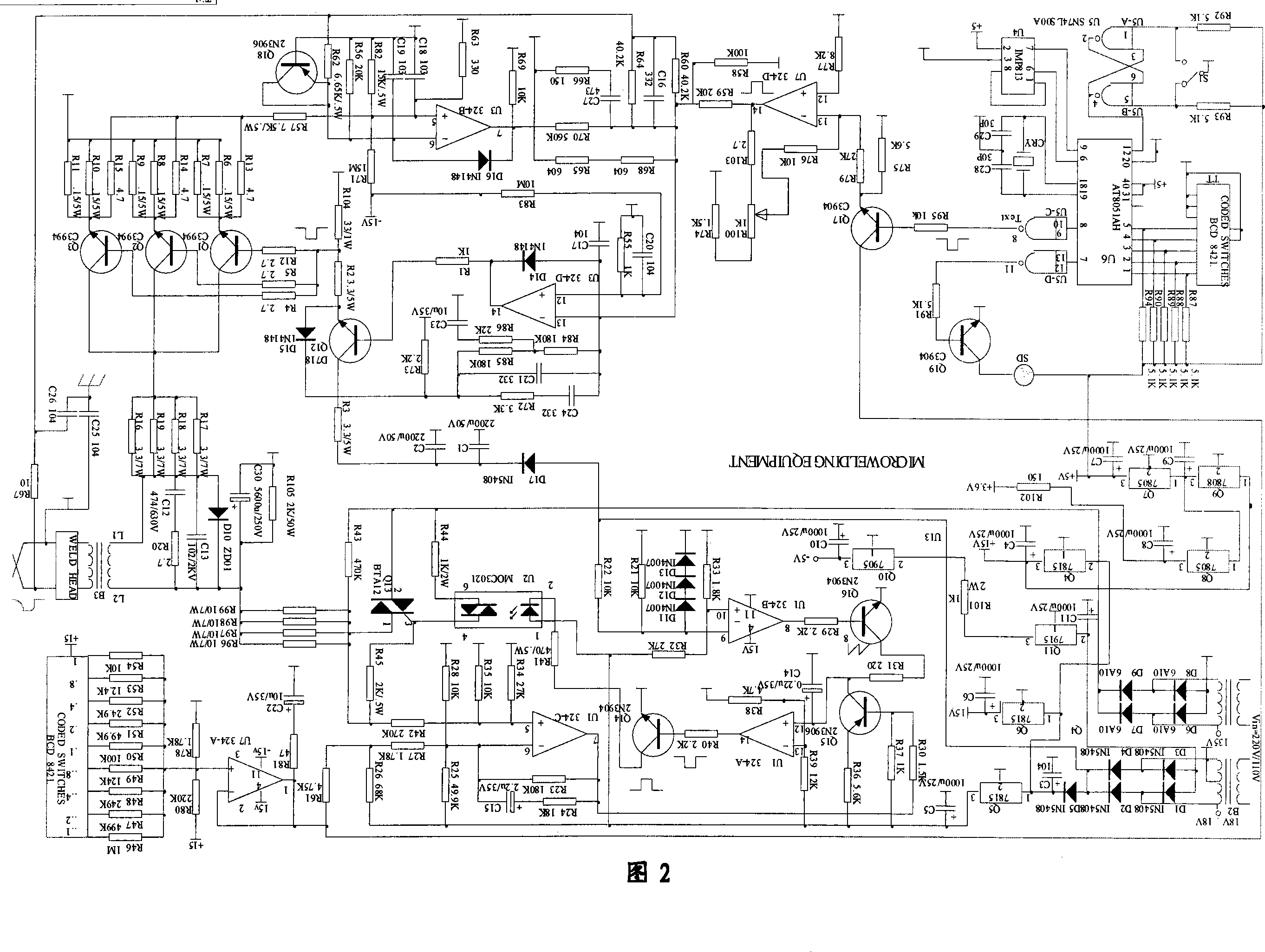
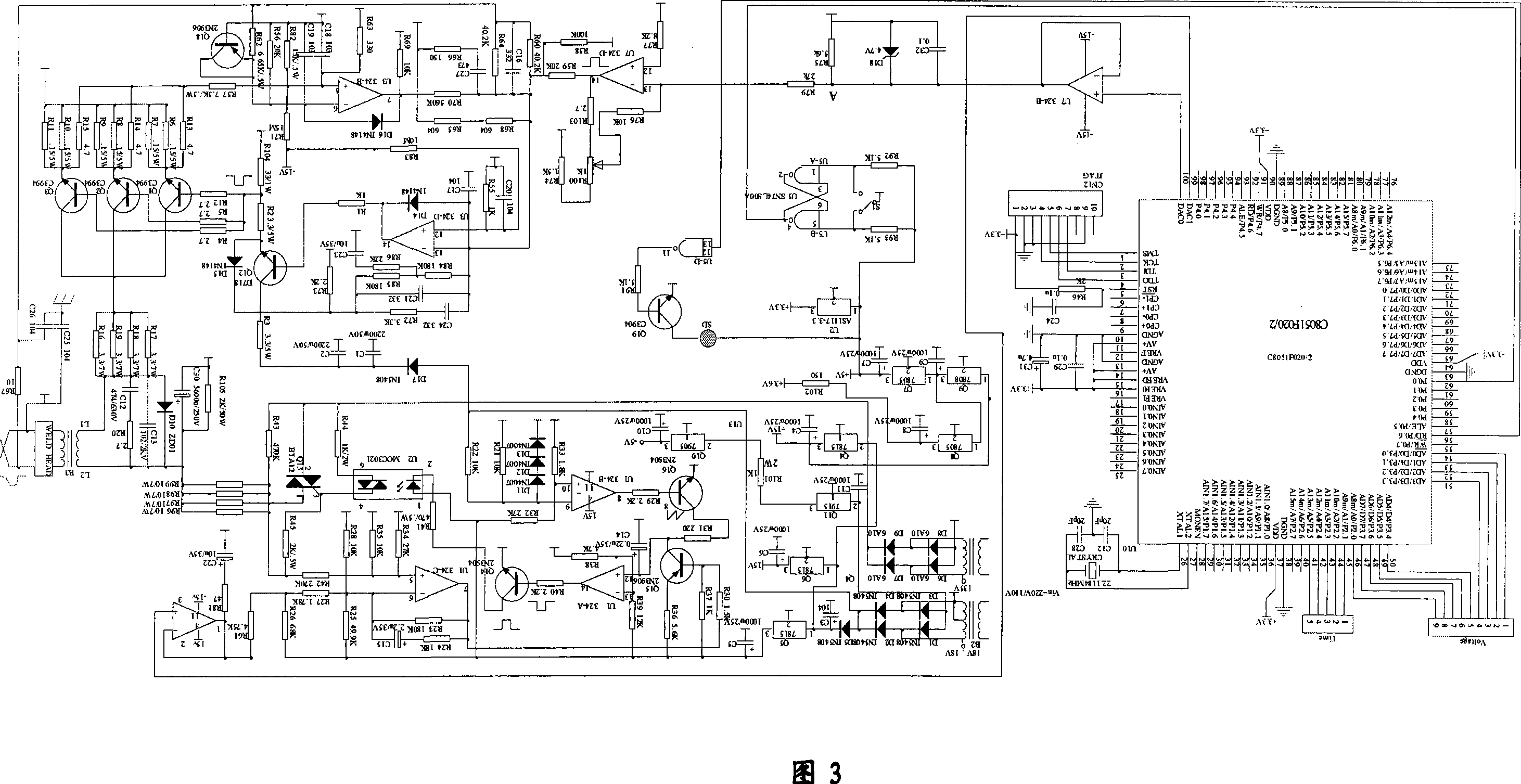
[0025] The specific implementation of the precision resistance welding spot welding machine of the present invention will be described in detail below in conjunction with the accompanying drawings.

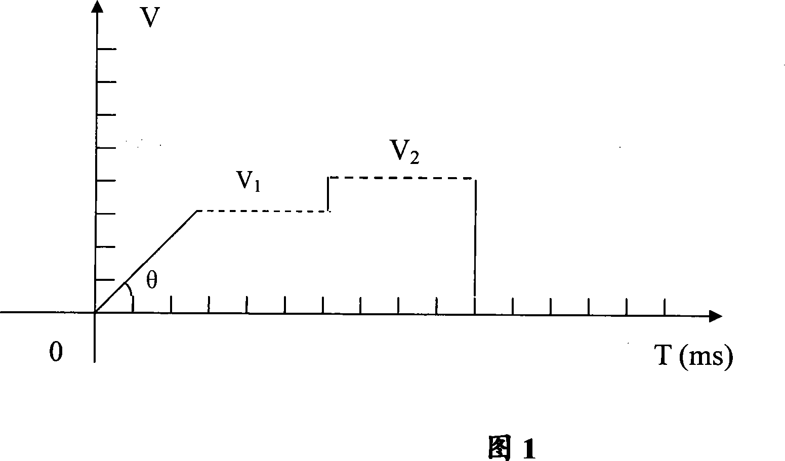
[0026] To directly weld the enameled wire, it is generally necessary to use a prestressed spot welding electrode (patent No. 93245377.5), a spot welding tip (patent No. 01114808.X) or a resistance welding tip and its preparation method (patent No. 2005121259.2). head. Judging from the structures of these welding heads, the tips of the two electrodes that constitute the welding head are stress contact ohmic contact or conjoined. After a lot of experiments, research and analysis, the present invention finds that the principle of direct welding enameled wire can be summarized as follows: when welding, conduction current, because there is an insulating layer on the enameled wire, the current all flows through the tips of the two electrodes of the welding head, so that the tip of the w...


PUM


Abstract

The invention relates to a precision resistant welding spot-welder which is mainly used for welding enamel wire extraction contacts and minimal work pieces in the manufacturing of electric elements with small coils and comprises main power supply, a welding head and a die; among which, the main power supply which comprises a resistant welding transformer and a power supply control device provides step wave pulse output and outputs suitable current for welding through the power supply control device; the die connects the welding head and the output through the resistant welding transformer and provides welding power. The resistant welding spot welder output by the step wave of the invention reduces the damages to the welding head caused by excessive current which is used for burning the insulating varnish of the enamel wire and prolongs the service life of the welding head.

Description

technical field [0001] The invention relates to a precision resistance welding spot welding machine in the production equipment of electronic components, which is mainly used in the welding of enameled wire lead-out contacts in the production of various electronic components with small coils, and can also be applied to the welding of various fine workpieces Precision welded. Background technique [0002] The technology of directly welding enameled wire is a new technology. The applicant of this patent has successively applied for a spot welding machine (patent No. 01114785.7), a spot welding head (patent No. 01114808.X) and a prestressed spot welding electrode which can directly weld enameled wire. (Patent No. 93245377.5), resistance welding head and its preparation method (Patent Application No. 2005121259.2), spot welding machine head with pressure display (Patent No. 01114856.X), spot welding head clamp (Patent No. 01114831.4), Welding head clamp with light source (paten...

Claims


Application Information

Patent Timeline
IPC IPC(8): B23K11/11B23K11/24B23K11/26H01R43/02
Inventor 杨仕桐
Owner 杨仕桐
Why Eureka
Try Eureka