Substrate cutting splitting device and method

A technology for substrates and slivers is applied in the field of substrate cutting and slicing devices, which can solve the problems of manpower and time consumption, and achieve the effects of reducing the burden and reducing the cost of artificial slicing.

Inactive Publication Date: 2008-08-06
AU OPTRONICS CORP
View PDF0 Cites 29 Cited by
  • Summary
  • Abstract
  • Description
  • Claims
  • Application Information

AI Technical Summary

Problems solved by technology

[0004] This kind of slitting manufacturing process, after the glass substrate is cut, is mostly manually sli

Method used


Image

  • Substrate cutting splitting device and method
  • Substrate cutting splitting device and method
  • Substrate cutting splitting device and method

Examples


Embodiment Construction

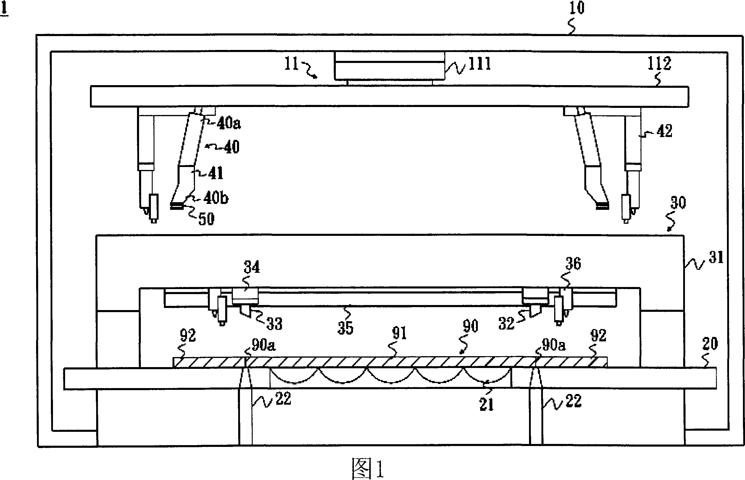
[0052] FIG. 1 is a schematic diagram of a substrate cutting and splitting device of the present invention. The substrate cutting and splitting device 1 includes: a frame body 10 , a mounting table 20 , a cutting unit 30 , a connecting arm 40 and a suction nozzle 50 .

[0053] The frame body 10 is approximately a rectangular frame, and a rotating mechanism 11 is provided on the top. The rotating mechanism 11 is provided with a rotating unit 111 and an arm 112 . The rotating unit 111 is connected to the frame body 10 and can drive the arm 112 to rotate.

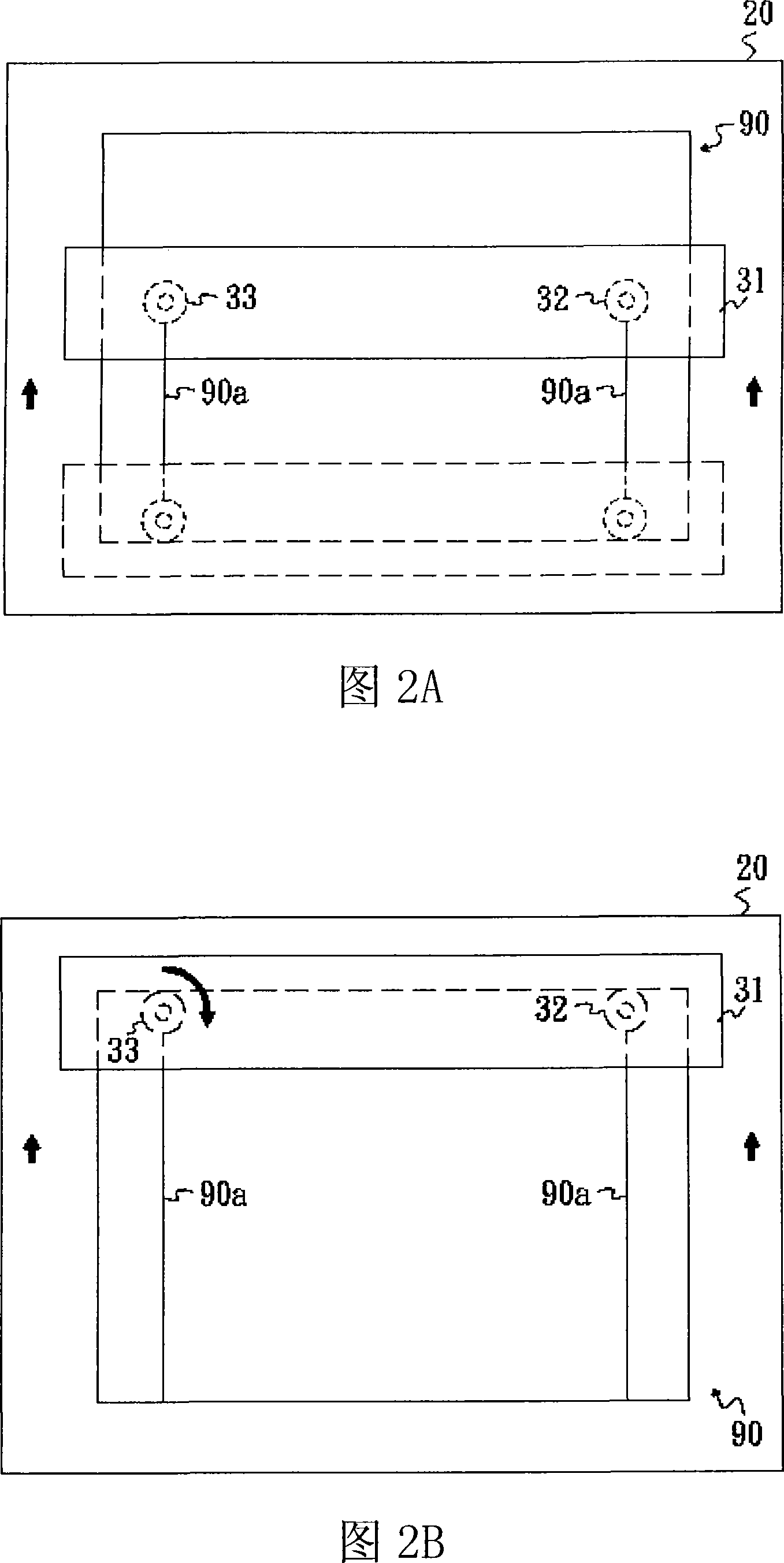
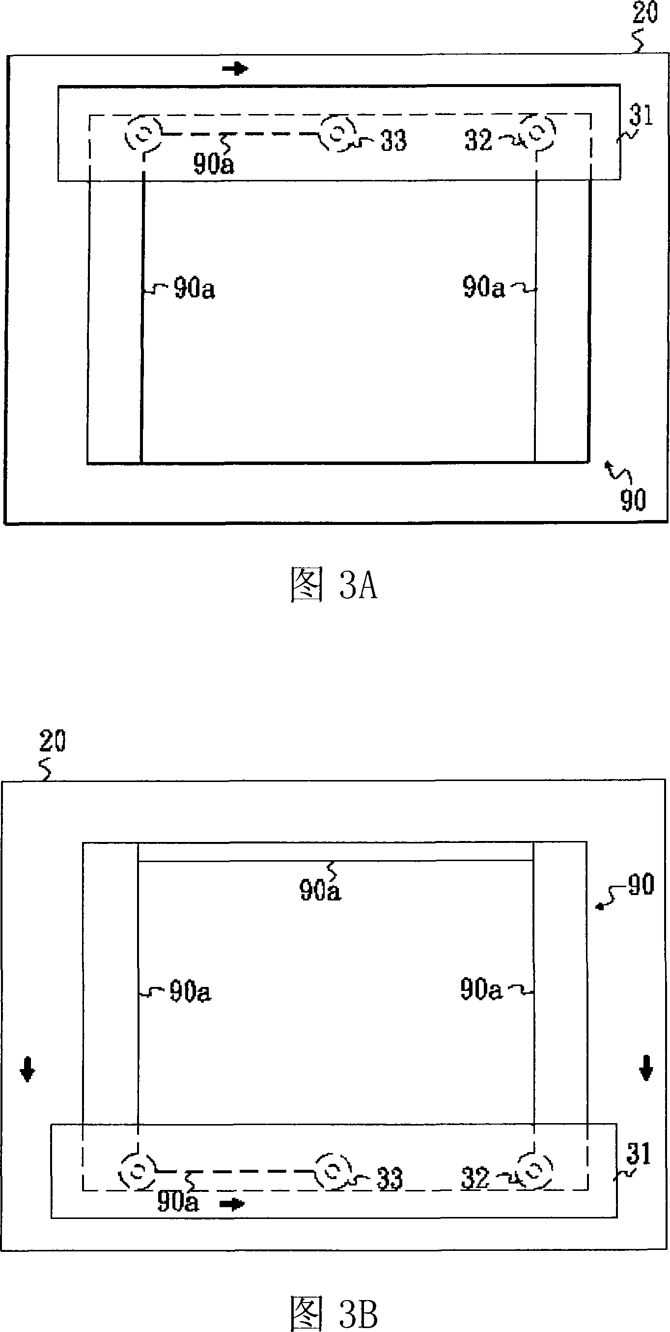
[0054] The mounting platform 20 is located in the frame body 10 for carrying the substrate 90 . The stage 20 is provided with a plurality of adsorption elements 21 , which can absorb the substrate 90 by vacuum, so that the substrate 90 is fixed on the stage 20 without shaking or shifting. The substrate 90 can be made of glass, but not limited thereto, and those skilled in the art can also select an appropriate substrate materi...


PUM


Abstract

The invention discloses a method for cutting lobes from a substrate, which comprises a substrate is supported ; at least a cutting mark is formed on the cutting substrate so as to divide the substrate into a body and at least a residual material; a link arm is moved to above the residual material and then is driven to realize displacement so as to drive a suction nozzle to adsorb the residual material; then the link arm is driven to stress force, thus cutting the residue material along the cutting mark. A device for cutting the lobes from the substrate is also disclosed.

Description

technical field [0001] The invention relates to a cutting and splitting device and method, in particular to a substrate cutting and splitting device and method. Background technique [0002] Due to the development of scientific and technological information products towards the goal of being light, thin, short, and small, traditional cathode ray tube screens are limited by problems such as large size and large energy consumption, which cannot meet the actual needs of users and are gradually eliminated by the market. , and replaced by a liquid crystal display (liquid crystal display, LCD) which has the advantages of small size and low power consumption. [0003] In order to meet different usage requirements, the size of the liquid crystal display panel also varies with the demand. Therefore, during the processing of the liquid crystal display panel, it needs to go through the process of cutting and splitting, that is, in order to obtain the required specifications, it will be...

Claims


Application Information

Patent Timeline
IPC IPC(8): C03B33/02
Inventor 吴国华简维谊黄宏基徐士峰王书志
Owner AU OPTRONICS CORP
Why Eureka
Try Eureka