Parallel flow heat converter dedicated for air conditioner

An exchanger and flow heat technology, applied in the field of parallel flow heat exchangers, can solve problems such as limited space, influence on popularization and application, and failure to achieve heat exchange, etc., to eliminate all shortcomings, reduce production costs, and have large heat exchange capacity Effect

Inactive Publication Date: 2008-08-06
孙海潮
View PDF0 Cites 3 Cited by
  • Summary
  • Abstract
  • Description
  • Claims
  • Application Information

AI Technical Summary

Problems solved by technology

However, there are still some shortcomings in the technical structure of the existing parallel flow heat exchanger, which seriously affects its wider application.
The most notable disadvantage is that the headers in the existing parallel flow heat exchangers are all straight cylindrical tubes, that is, the central connection line of the cross section of the headers is a straight line, which determines the parallel flow heat exchange. The shape of the device can only be flat and straight
However, some heat exchanger applications have very limited space, and there are strict restrictions on the expansion of the heat exchanger plane. The planar straight plate parallel flow heat exchanger designed according to these limited space sizes cannot meet the required heat exchange capacity. , only by expanding the application space can it be used in this type of heat exchanger application, but this will increase the production cost and lose the advantages of compact structure and low cost of parallel flow heat exchangers, and in most cases this application is impossible According to the expansion of requirements, this limits the alternative use of parallel flow heat exchangers in these special occasions. Furthermore, air conditioner heat exchangers need to use fans to force air convection. For some fans, such as cross-flow fans, Centrifugal fans, etc., have special air inlet and outlet structures, and the forced air convection effect combined with the flat straight plate parallel flow heat exchanger is poor, and the required heat exchange purpose cannot be achieved.

Method used


Image

  • Parallel flow heat converter dedicated for air conditioner
  • Parallel flow heat converter dedicated for air conditioner

Examples


Embodiment Construction

[0020] Below in conjunction with accompanying drawing and embodiment the present invention will be further described:

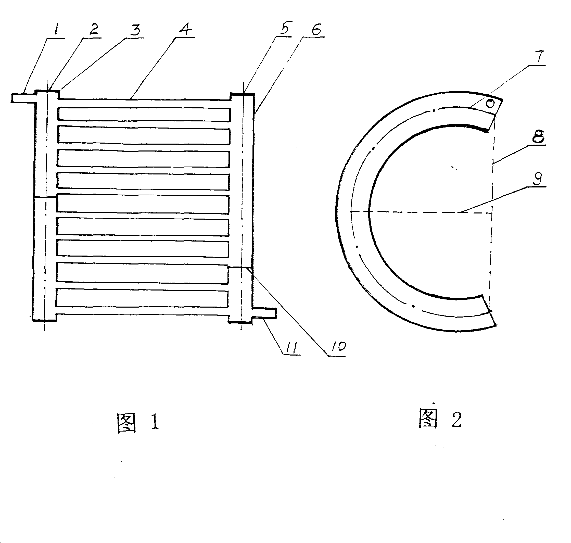
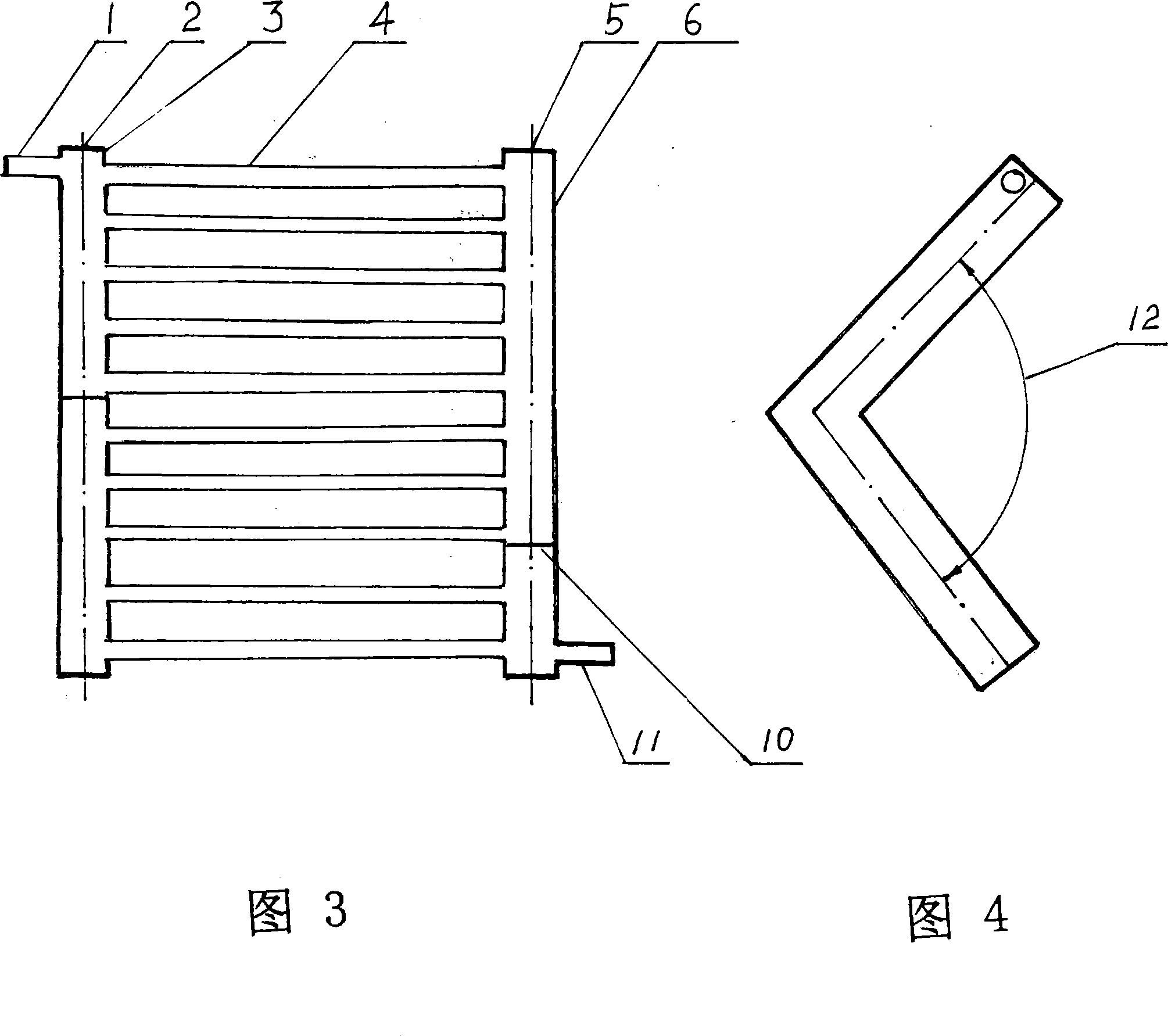
[0021]In the figure, 1 is the refrigerant inlet pipe, 2 is the centerline of the arc-shaped collector, 3 is the arc-shaped collector, 4 is the heat exchange flat tube, and 5 is the centerline of the arc-shaped collector. , 6 is the arc type collector, 7 is the connecting line of the center point of the side projection of the arc type collector, 8 is the chord line, 9 is the arc height, 10 is the spacer, 11 is the refrigerant outlet pipe, 12 is angle.

[0022] This embodiment is an embodiment of the application of the arc type parallel flow heat exchanger of the present invention as an air conditioner condenser: see Fig. 1 and Fig. 2 . Figure 2 clearly shows the structure of the arc collector. 3 and 6 in the figure are a pair of arc-shaped collectors, 2 in the figure is the centerline of the orthographic projection of the arc-shaped collector 3, and 5 in the...


PUM


Abstract

A parallel flow heat exchanger specialized for air conditioner comprises a row of heat exchanging flat tubes parallel arranged. Two ports of the heat exchanging flat tubes parallel arranged are perpendicularly connected with a pair of collecting tubes, and the parallel flow heat exchanger is characterized in that the collecting tubes are of an arc shape, a connecting line of center points of cross sections of the arc shaped collecting tubes is a segment of an arc, the string length of the arc ranges from 0 to 6 times in arc height, and when projections of the connecting lines of the center points of cross sections of a pair of the arc shaped collecting tubes are straight lines, the parallel flow heat exchanger is of a parallel line structure. The invention can devote to design the parallel flow heat exchanger, completely meeting the heat exchanging capacity without changing the size of the exiting space, to be applied to heat exchanger occasions, on which the existing parallel flow heat exchanger can not be substituted in use. The parallel flow heat exchanger also can carry out target-oriented fit design for the structure of air outlets of forced an air convection fan when in heat exchanging, thereby largely increasing the heat exchanging efficiency. The parallel flow heat exchanger further has high heat exchanging capacity without cup weld of radiating aluminum sheets, thereby eliminating all the defects brought by the radiating aluminum sheets.

Description

[0001] The invention relates to a parallel flow heat exchanger specially used for air conditioners, in particular to a parallel flow heat exchanger specially used for air conditioner headers. Background technique [0002] Currently known air conditioner heat exchangers are generally divided into three types according to the tube shape and structure of the heat exchange tubes used, tube-belt type and parallel flow type. The agent is introduced into the pipe made into a certain shape to flow. While flowing, the purpose of heat exchange is achieved by exchanging heat with the air outside the pipe. In order to achieve the required heat exchange capacity, it is necessary to weld the heat dissipation aluminum on the outside of the pipe. Sheet, and equipped with fan forced air convection. Among them, the basic technical characteristics of the parallel flow heat exchanger are: a number of parallel heat exchange flat tubes are vertically connected between a pair of parallel arranged he...

Claims


Application Information

Patent Timeline
Patent Type & Authority Applications(China)
IPC IPC(8): F25B39/00
Inventor 孙海潮
Owner 孙海潮
Why Eureka
Try Eureka