Mould shell component shaping mould

A formwork component and forming mold technology, applied in the direction of molds, mold separation devices, etc., can solve the problems of inconvenient demoulding and easy damage of thin-walled boxes

Inactive Publication Date: 2008-08-13
湖南邱则有专利战略策划有限公司
View PDF2 Cites 1 Cited by
  • Summary
  • Abstract
  • Description
  • Claims
  • Application Information

AI Technical Summary

Problems solved by technology

Such as the positive mold, as can be seen from their drawings, it includes a side mold surface and a lower mold surface (or a top mold surface), and the side mold surface and the lower mold surface form a male mold, which is the male mold of the overall template. In the actual use process, it is inconvenient to demould, and the open thin-walled tube or thin-walled box is easy to be damaged. Therefore, it is urgent to develop a new type of mold shell component forming mold.

Method used


Image

  • Mould shell component shaping mould
  • Mould shell component shaping mould
  • Mould shell component shaping mould

Examples


Embodiment Construction

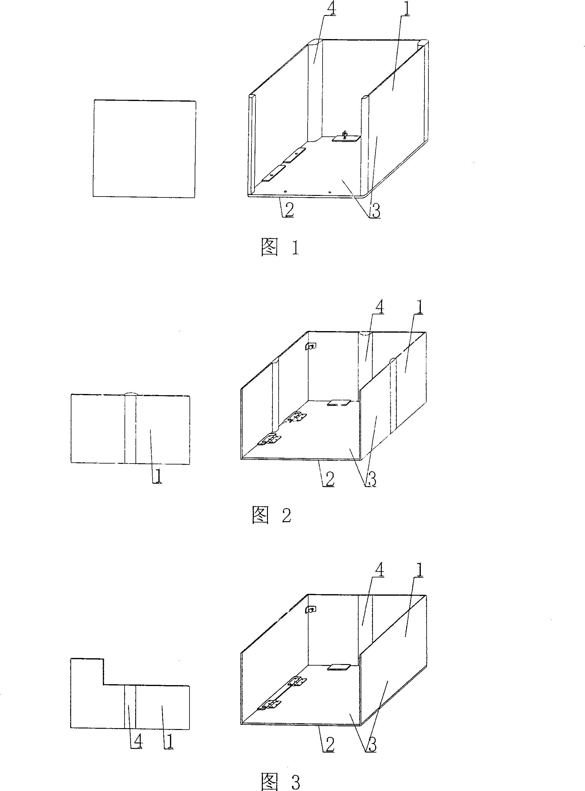
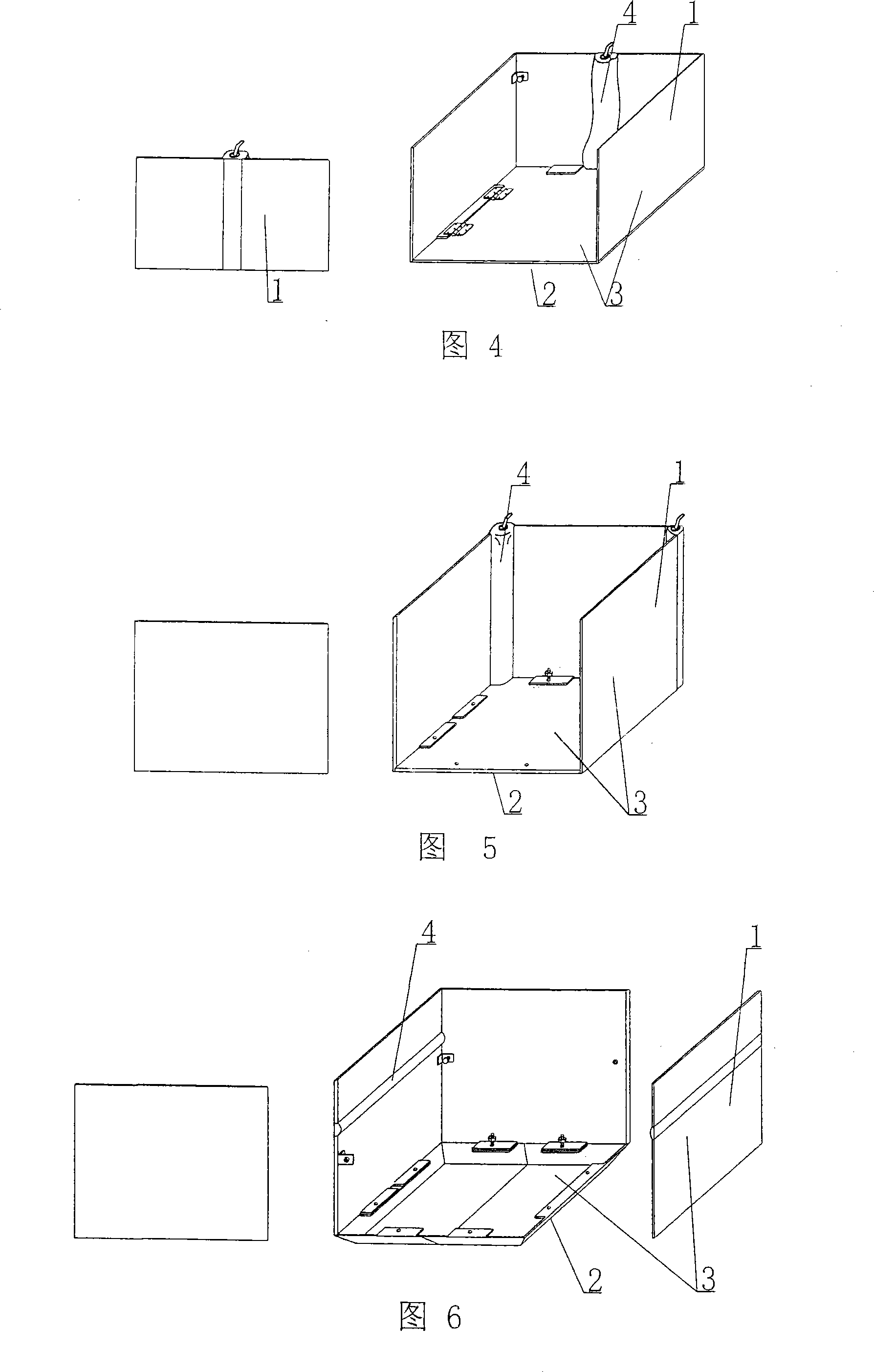
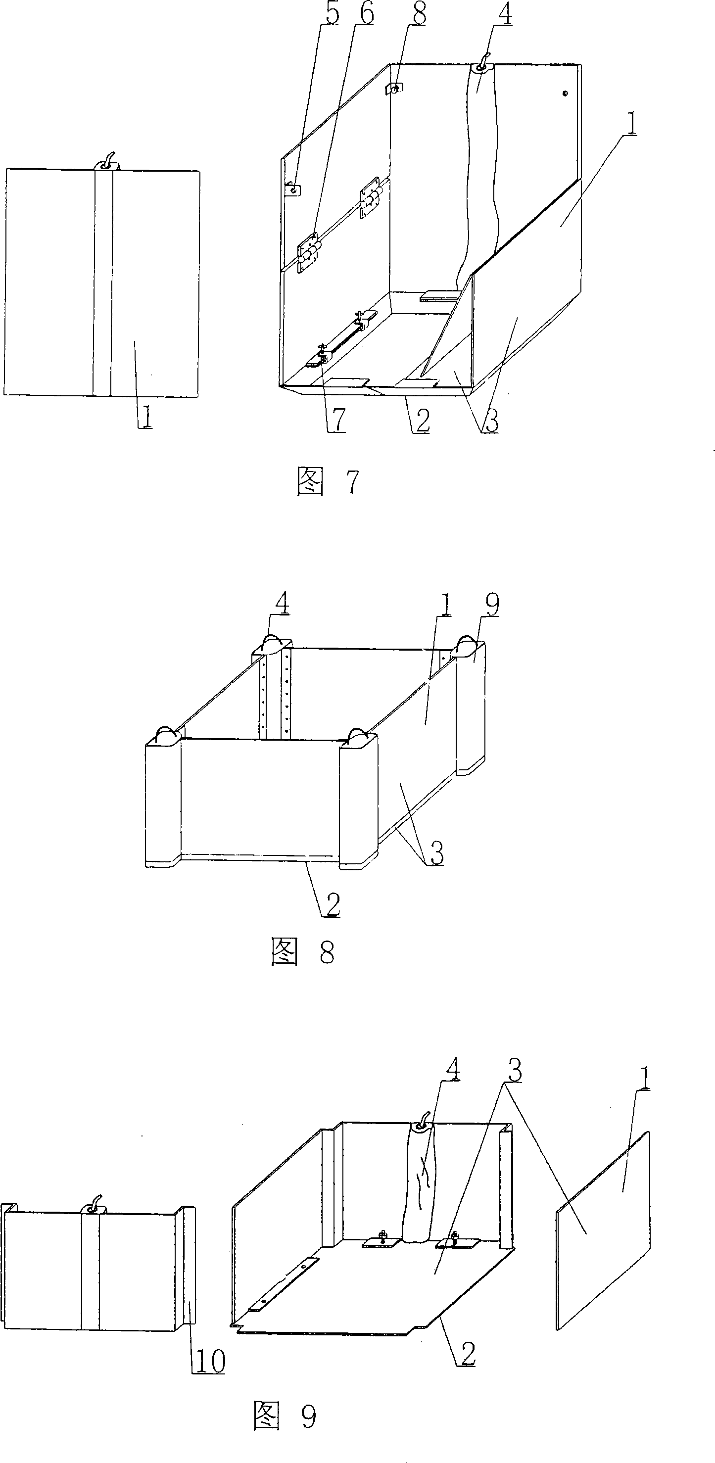
[0064] The present invention will be further described below in conjunction with the accompanying drawings and embodiments.

[0065] As shown in the accompanying drawings, the present invention includes a side mold surface 1 and a lower mold surface 2, and the side mold surface 1 and the lower mold surface 2 form a male mold, and is characterized in that the side mold surface 1 and the lower mold surface of the male mold 2 is composed of a template 3, the male mold is composed of a lower mold surface template and four side mold surface templates, and at least one stretchable elastic part 4 is arranged on the combined template 3. In each accompanying drawing, 1 is a side mold surface, 2 is a lower mold surface, 3 is a template, and 4 is an elastic component. In the following accompanying drawings, those with the same number have the same description. As shown in Figure 1, the side mold surface 1 and the lower mold surface 2 are surrounded by a male mold, and the side mold surfa...


PUM


Abstract

A forming die for shuttering components comprises a side die surface (1) and a lower die surface(2). A positive mold consists of the side die surface(1) and the lower die surface(2), characterized in that the side die surface(1) and the lower die surface(2) of the positive mold are made of moulding boards(3), so that the positive mold consists of one lower die surface moulding board and four side die surface moulding boards on which at least one telescopic resilient mean is mounted, so as to work for manufacturing thinwalled tubes or thinwalled boxes, particularly ones having openings.

Description

[0001] This application is a divisional application of an invention patent application with the filing date of February 27, 2004, the application number of 200410005686.X, and the title of "a mold for molding shell components". (1) Technical field [0002] The invention relates to a mold for molding shell components. (2) Background technology [0003] At present, cast-in-place reinforced concrete hollow slabs, especially the non-core-pulling hole-forming process of cast-in-situ reinforced concrete hollow slabs, are generally filled with thin-walled tubes or thin-walled boxes, which can meet the needs of various hollow slabs for evacuating concrete. The applicant applied for an invention patent with the application number 99115665.X and the title "fiber-reinforced thin-walled pipe (box) for reinforced concrete filling and its manufacturing method" on November 29, 1999, and the application number 99115666.8 , the invention patent titled "fiber-reinforced thin-walled box for fi...

Claims


Application Information

Patent Timeline
IPC IPC(8): B28B7/22B28B7/06B28B7/26B28B7/02
Inventor 邱则有
Owner 湖南邱则有专利战略策划有限公司
Why Eureka
Try Eureka