Circulating fluid bed boiler furnace possessing heating screen

A circulating fluidized bed and boiler furnace technology, applied in steam boilers, lighting and heating equipment, steam generation, etc., can solve the problems of furnace material concentration, temperature distribution, heat transfer uniformity, and furnace material circulation. Complete combustion and low NOx emissions

Active Publication Date: 2008-08-13
INST OF ENGINEERING THERMOPHYSICS - CHINESE ACAD OF SCI
View PDF0 Cites 19 Cited by
  • Summary
  • Abstract
  • Description
  • Claims
  • Application Information

AI Technical Summary

Problems solved by technology

[0004] However, because the existing technology separates the furnace bed surface, and some also have a heating surface that separates the upper space of the furnace, th

Method used


Image

  • Circulating fluid bed boiler furnace possessing heating screen
  • Circulating fluid bed boiler furnace possessing heating screen
  • Circulating fluid bed boiler furnace possessing heating screen

Examples


Embodiment 1

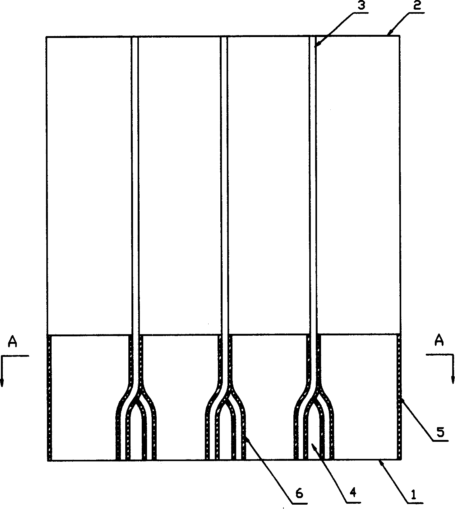
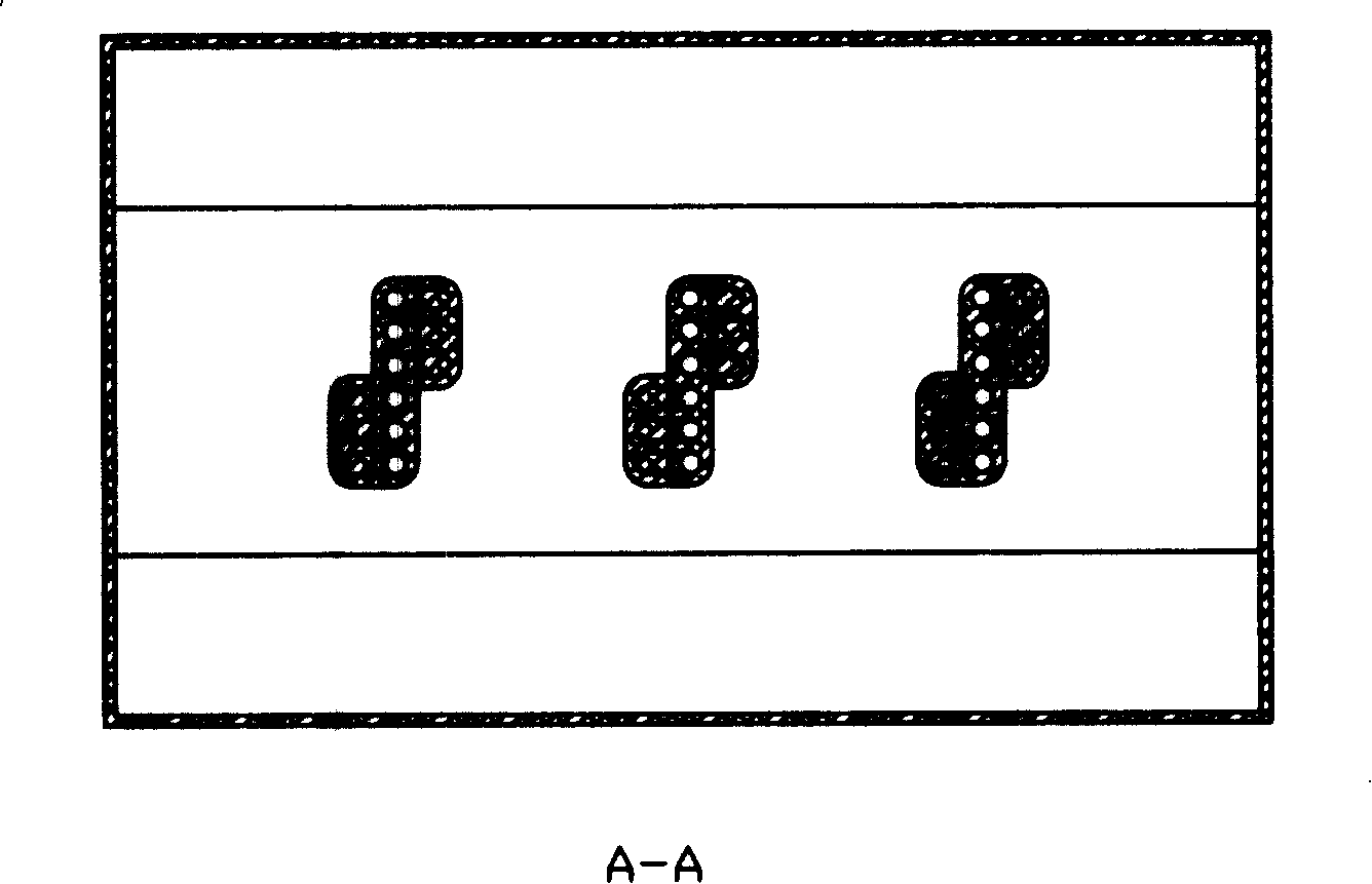
[0027] Such as figure 1 and figure 2 As shown, in the furnace of a circulating fluidized bed boiler with a heating screen, three heating screens 3 with the same height as the furnace and equally spaced and parallel to each other are arranged between the furnace air distribution plate 1 and the ceiling 2. The heating screen 3 consists of a membrane wall Composition, the working medium is passed through the membrane wall tube from bottom to top, the upper part of the heating panel 3 is vertical, and the lower part of the membrane wall tube is divided into two parts, which respectively let the tube flow in two directions perpendicular to the surface of the heating panel 3. , forming a "herringbone" space 4 connecting the front and back of the screen. The lower part of the heating screen 3 is laid with a wear-resistant material 6 of the same height as the wear-resistant layer 5 at the lower part of the furnace water wall.

Embodiment 2

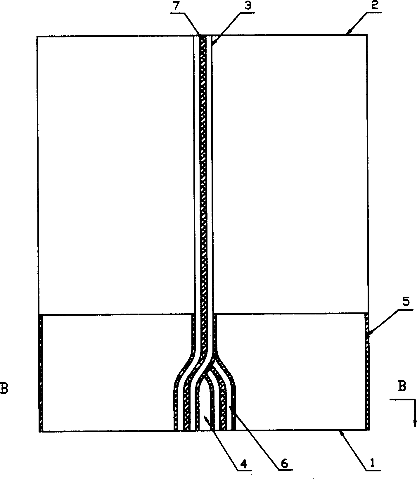
[0029] Such as image 3 and Figure 4 As shown, in the furnace of a circulating fluidized bed boiler with a heating screen, a heating screen 3 with the same height as the furnace is arranged between the furnace air distribution plate 1 and the ceiling 2. The heating screen 3 is composed of two membrane walls that are closely attached together. Each membrane wall has only one side facing the combustion space of the furnace; the two membrane walls are fixed with a comb-shaped plate (not shown in the figure) and filled with refractory material 7; the inside of the membrane wall tube is bottom-up There is a working medium, the upper part of the heating screen 3 is vertical, and the lower part keeps two membrane walls close together, divides the width into four equal parts, and alternates the tubes in two directions perpendicular to the surface of the heating screen 3, forming three Connect the "herringbone" space 4 before and after the screen. The wear-resistant material 6 is la...

Embodiment 3

[0031] Such as Figure 5-7 As shown, for a circulating fluidized bed boiler furnace with heating panels, there are three heating panels 3 with the same height as the furnace and the upper part on the same plane between the furnace air distribution plate 1 and the ceiling 2. Each heating panel 3 is composed of two Each membrane wall has only one side facing the furnace combustion space; the two membrane walls are fixed with a comb-shaped plate (not shown in the figure) and filled with refractory material ( Not shown in the figure); there is a working fluid in the membrane wall tube from bottom to top, the upper part of the heating screen 3 is vertical, and the lower part is a square cylindrical space 8 formed by two membrane walls in different directions to allow the tube to surround and synthesize , the cylinder is made of a single-layer membrane wall, and the combustion wind is passed into the column, and the cylinder is provided with an air port (not shown in the figure); th...


PUM


Abstract

The present invention provides a circulating fluidized bed boiler furnace having heated screen, the heated screen is set between the furnace grid plate and the ceiling which height is identical to the furnace, the heated screen is made of membrane panel, membrane panel pipe has working substance un-down, the upper of the heated screen is vertical, the lower has space connected the front and the back screen formed by pipe; the heated screen is one or more plates. The circulating fluidized bed boiler furnace having heated screen gives space to the material cycle when the furnace provides extending heated surface, ensuring the uniformity of the material concentration, temperature and heat transfer; secondary air inlets in the center of the furnace, fullu burning, and has lower NOx drainage.

Description

technical field [0001] The invention relates to a circulating fluidized bed boiler, in particular to a circulating fluidized bed boiler furnace with extended heating panels. Background technique [0002] With the expansion of boiler capacity, more heating surfaces need to be arranged in the furnace of circulating fluidized bed boilers to maintain a reasonable bed temperature and flue gas temperature at the furnace outlet. At the same time, the larger the boiler capacity, the larger the cross-sectional area of ​​the furnace, and the difficulty for the secondary air to penetrate the furnace also increases, and the center of the furnace is prone to form an oxygen-deficient area. [0003] In order to solve this problem, in large boilers, especially supercritical boilers, the existing technology generally adopts the method of setting partitions at the lower part of the furnace to divide the bed surface into two or more parts, and the partitions are provided with tuyeres. Seconda...

Claims


Application Information

Patent Timeline
IPC IPC(8): F22B31/08
Inventor 吕清刚包绍麟高鸣孙运凯宋国良那永洁王东宇贠小银李诗媛
Owner INST OF ENGINEERING THERMOPHYSICS - CHINESE ACAD OF SCI
Why Eureka
Try Eureka