
Laser self-adjusting demarcation device

A line casting and self-adjusting technology, applied in instruments, measuring instruments, measuring devices, etc., can solve the problems of small adjustment range, high cost, poor accuracy, etc., to improve safety and reliability, prolong service life, and have a reasonable and practical structure. Effect

Inactive Publication Date: 2008-08-13
陈建军
View PDF2 Cites 13 Cited by
  • Summary
  • Abstract
  • Description
  • Claims
  • Application Information

AI Technical Summary

Problems solved by technology

Its defect is: the 90-degree adjustment structure between the vertical laser heads is too simple, the adjustment range is relatively small, and, in the adjustment process, it is easy to interfere with the verticality of the laser line, on the contrary, the horizontal adjustment mechanism of the vertical laser head is too complicated , the level adjustment device composed of variable speed motor, deceleration mechanism and screw rod is not worth the gain, resulting in large volume, high cost and other defects
[0004] For example, the Chinese patent "Laser Line Projector" with the patent number of 200520076200.1 has the advantages of flexible rotating mechanism and can be freely changed in many ways. Due to the small number of laser heads, the defect is that it cannot cast the cross horizontal line and vertical line at the same time, which limits certain It is used on occasions, and the accuracy may be worse

Method used


Image

  • Laser self-adjusting demarcation device
  • Laser self-adjusting demarcation device
  • Laser self-adjusting demarcation device

Examples


Embodiment Construction

[0036] The present invention will be further described in detail below in conjunction with the accompanying drawings and embodiments.

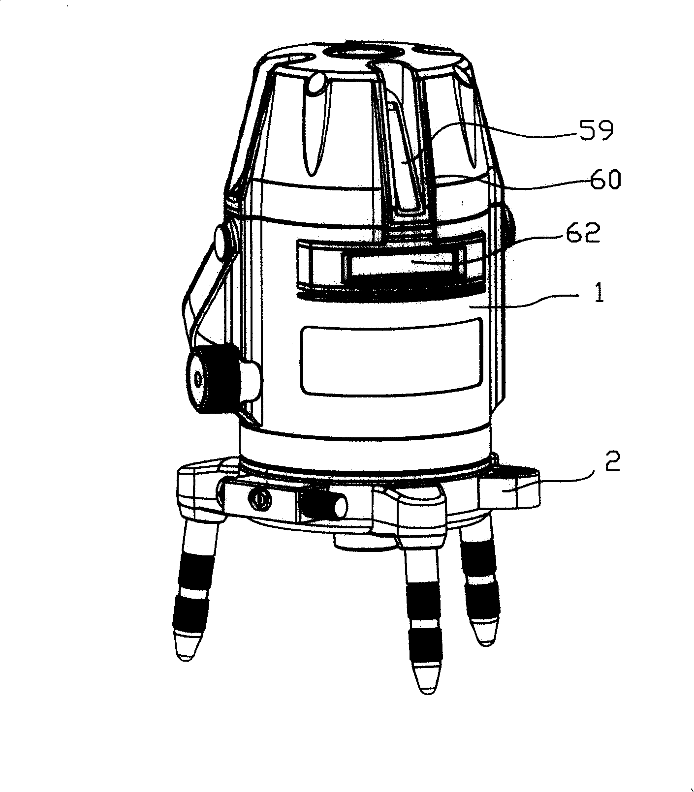
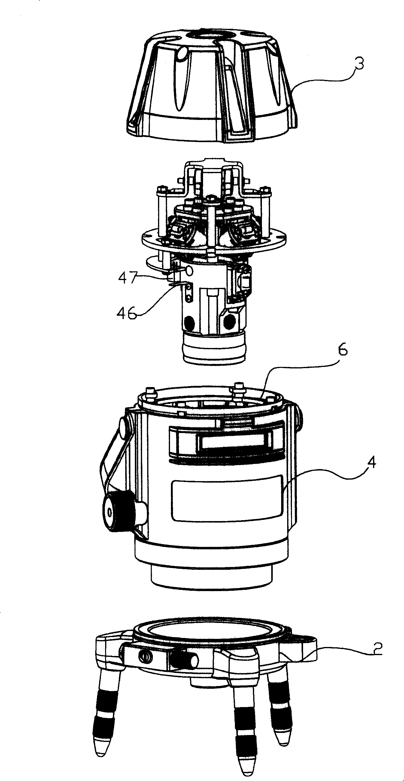
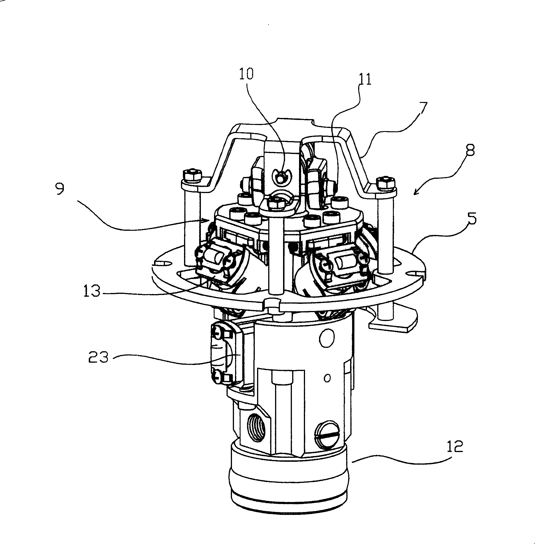
[0037] As shown in the figure, the figure numbers are: shell 1, base 2, upper cover 3, main shell 4, fixed ring 6, support frame 7, hanging body 8, movement 9, upper shaft 10, lower shaft 11, weight Hammer part 12, vertical laser head seat 13, laser head 14, hanging body top plate 15, screw 16, lug 17, screw 18, elastic notch 19, screw 20, installation cavity 21, pin 22, horizontal laser head seat 23. Locking screw 24, horizontal laser head 25, screw hole 26, perforation 27, screw 28, spring 29, opening 30, down-shooting laser head 31, elastic ring 32, non-magnetic screw 33, damping sleeve 34, light-emitting hole 35. Shaft pin 36, supporting plate 37, opening 38, rubber ring 39, locking knob 40, eccentric column 41, weight screw 42, spring fixing seat 43, micro switch 44, contact lever 45, photoelectric sensor Sheet 46, photocell 47, spring 4...


PUM


Abstract

The invention relates a laser self-tuning line-vote, which comprises a shell and a base, a heavy hammer part lay automatically is connected and installed on the inside of the shell through the hoisting bodies, four vertical laser head blocks is installed on main part of the heavy hammer part along ring distribution, a vertical line laser head is installed on each laser head block, and the angle between the laser head is 90 degrees, a vertical laser window is installed on the shell targeted, power and control circuit boards are also installed, the invention is characterized in that the vertical laser head blocks are connected through a screw and pegged roof of hoisted bodies, at the same time, a dummy club is installed on both sides of the laser head block by pegged roof, which is connected to the screw, and the vertical laser block is collided by the screw, the invention can lead to four vertical laser head blocks in 90-degree angle, and achieve vertical and horizontal adjustment, and has good regulation, reasonable and practical structure.

Description

technical field [0001] The invention relates to a laser self-adjusting line throwing instrument. Background technique [0002] The laser line projector is a precision instrument that can project cross horizontal lines and vertical lines on the wall, ground and zenith, and is widely used in various construction occasions such as the interior decoration industry. In order to reduce the installation deviation of the laser head, each laser head generally adopts an adjustment mechanism. [0003] For example, the Chinese patent No. 200520070817.2 "Laser module adjustment device for line casting instrument includes several vertical line laser modules, and the several vertical line laser modules are fixed on an integral adjustment seat; The seat has an umbrella-shaped structure, and four mounting plates are evenly distributed on its conical surface. The four mounting plates are hollowed out. There are mounting holes facing upwards on the mounting plate, and the fixed laser module i...

Claims


Application Information

Patent Timeline
Patent Type & Authority Applications(China)
IPC IPC(8): G01C15/00
Inventor 陈建军
Owner 陈建军
Learn More