Eureka AIR delivers breakthrough ideas for toughest innovation challenges, trusted by R&D personnel around the world.

A flat converter and its making method

A commutator and flat-plate technology, applied in the field of flat-plate commutator and its preparation, can solve the problems of reduced cross-sectional area of ​​support body, complicated production process, unfavorable mold release, etc., to reduce requirements and production costs. , the effect of simple structure

Inactive Publication Date: 2008-08-13
张浩宇
View PDF1 Cites 1 Cited by
  • Summary
  • Abstract
  • Description
  • Claims
  • Application Information

AI Technical Summary

Problems solved by technology

However, the prior art recorded in this patent document still has the following problems: on the one hand, due to the cold punching of the "eight" structure on the commutator piece, the cold stamping die must have a corresponding special structure, and this inner large The special structure of the outer small is not conducive to the demoulding of the mold, which makes the production process complicated; and because the "eight" structure is more complicated, the number of such structures on the surface of the mold will not be set a lot, and with the increase of the number of such structures , the grasping strength between the commutator segment and the support body does not increase with the increase of the number, mainly because the increase of this structure directly leads to the reduction of the cross-sectional area of ​​the support body itself, which leads to the high-speed rotation of the commutator. At this time, the support body is easy to break at the "eight" structure and the commutator piece will fall off, resulting in production accidents

Method used


Image

  • A flat converter and its making method
  • A flat converter and its making method
  • A flat converter and its making method

Examples


Embodiment Construction

[0025] The present invention will be further described below in conjunction with the accompanying drawings and embodiments, but it should be noted that these embodiments are only used to illustrate the method of the present invention, rather than limiting the scope of the present invention thereto.

[0026] The structure of the flat plate commutator of the present invention will be illustrated and described below.

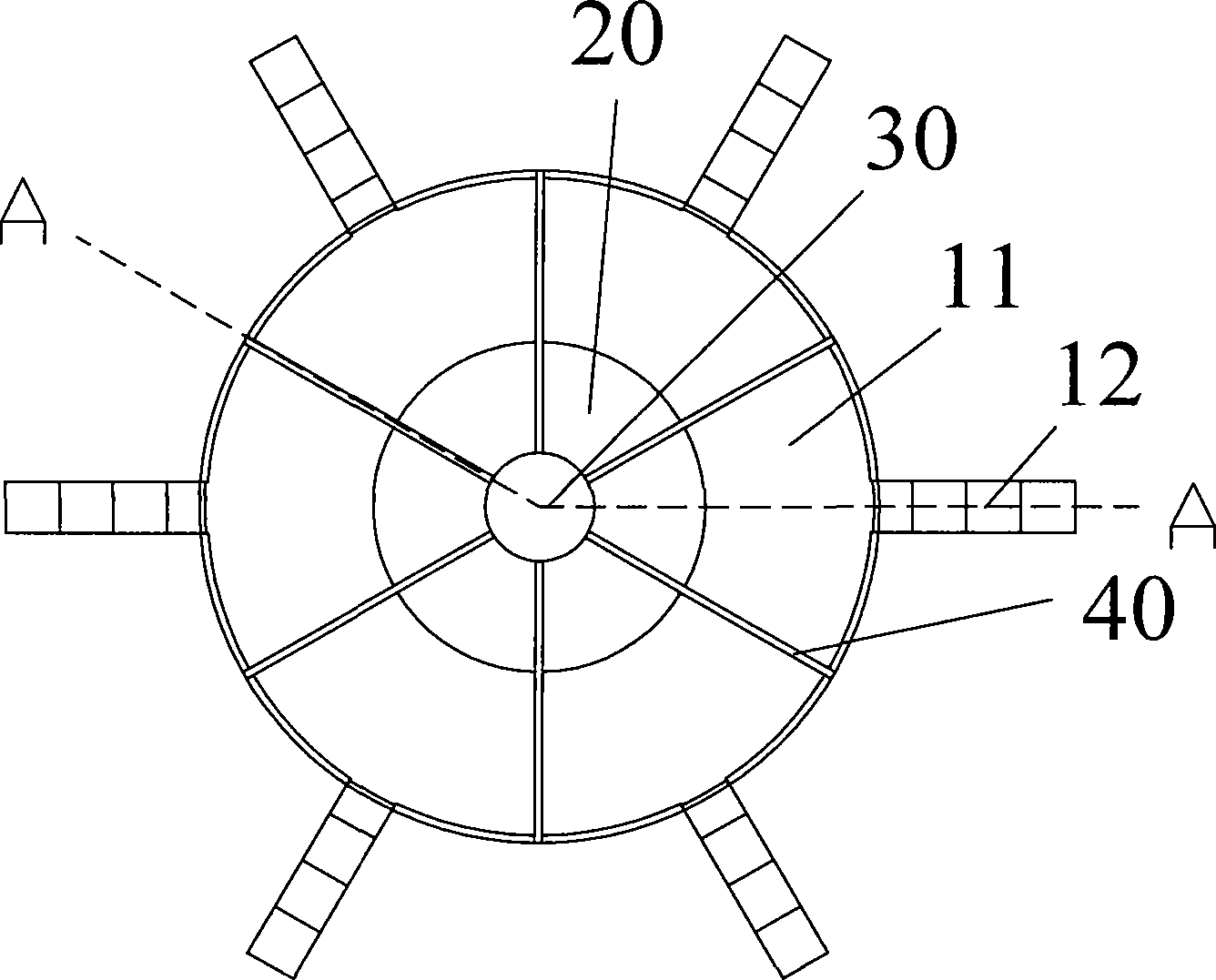
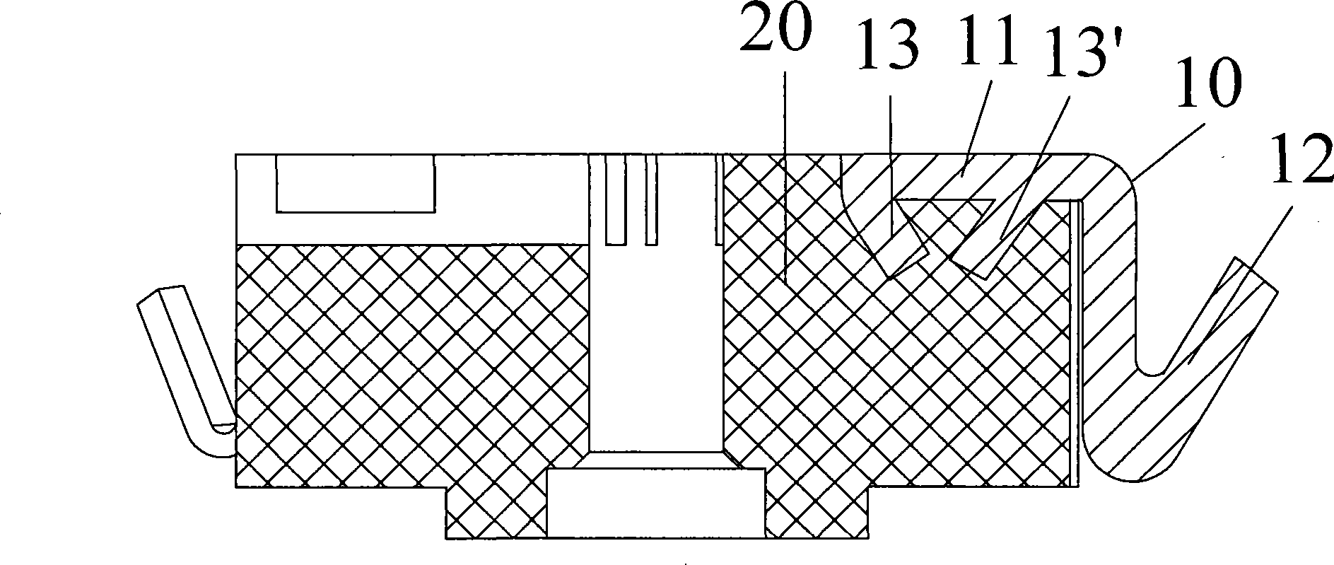
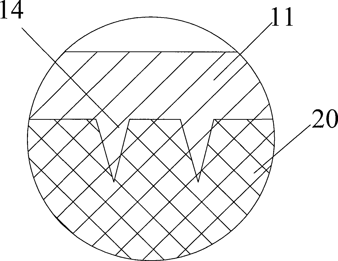
[0027] The flat commutator of the present invention mainly includes: an insulating support body 20 with a central axis hole 30, and a commutator body disposed on the end face of the support body 20, and the commutator body includes a plurality of commutator segments 10 , each of the commutator segments 10 includes a connecting hook 12 and a contact segment 11, the plane of the contact segment 11 is perpendicular to the central axis hole 30, and there is a radial groove 40 between adjacent commutator segments , to ensure that there is no conductive connection betwee...


PUM


Abstract

A plate type commutator comprises an insulating supporting body with a central axis hole, and a commutator body arranged on the end of the supporting body, the commutator body comprises a plurality of commutating segments, each commutating segment comprises a connecting hook and a contact segment, the side of the contact segment facing to the end plane of the supporting body is provided with a plurality of projections or dents, the area of the cross section of the projection gradually reduces to the direction of the supporting body, and the area of the cross section of the dent gradually reduces to the direction of the inner part of the contact segment. The method for manufacturing the plate type commutator comprises the following steps: a cold pressing step; a blanking step; a pressure-injecting procedure; and a groove milling and hook bending procedure. The plate type commutator of the invention can increase the contact strength between the commutating segment and the supporting body and has stable service behavior.

Description

technical field [0001] The invention relates to a flat commutator and a preparation method thereof. Specifically, it relates to a method for manufacturing a flat-plate commutator used in a motor and the commutator manufactured by the method. Background technique [0002] The existing flat-plate commutator usually has poor contact strength between the commutator segment and the insulating support, and there are phenomena of jumping and flying segments. Chinese patent document CN2583841Y discloses a structure of an all-plastic planar commutator. By setting a "eight"-shaped structure on the side of the commutator piece in contact with the bakelite, it is used to increase the contact strength between the commutator piece and the bakelite. In addition, the description of this document also discloses the preparation process of this kind of commutator: the commutator body is formed by cold extrusion of copper plate, the feet of the commutator segments are formed into a "eight" str...

Claims


Application Information

Patent Timeline
Patent Type & Authority Applications(China)
IPC IPC(8): H01R39/06H01R43/06
Inventor 张浩宇
Owner 张浩宇
Why Eureka
Eureka Blog
Learn More