Chip resistor

A chip resistor, resistive film technology, applied in resistors, resistor parts, non-adjustable metal resistors, etc., can solve the problems of low heat transfer to the printed substrate and high temperature of the resistive film

Active Publication Date: 2008-08-13
ROHM CO LTD
View PDF1 Cites 22 Cited by
  • Summary
  • Abstract
  • Description
  • Claims
  • Application Information

AI Technical Summary

Problems solved by technology

Therefore, this kind of chip resistor has the problem that the transferability of the heat generated mainly in the narrow portion of the resistive f

Method used


Image

  • Chip resistor
  • Chip resistor
  • Chip resistor

Examples


Embodiment Construction

[0024] Hereinafter, embodiments of the present invention will be specifically described with reference to the drawings. However, in these drawings, the same reference numerals are assigned to the same or similar components.

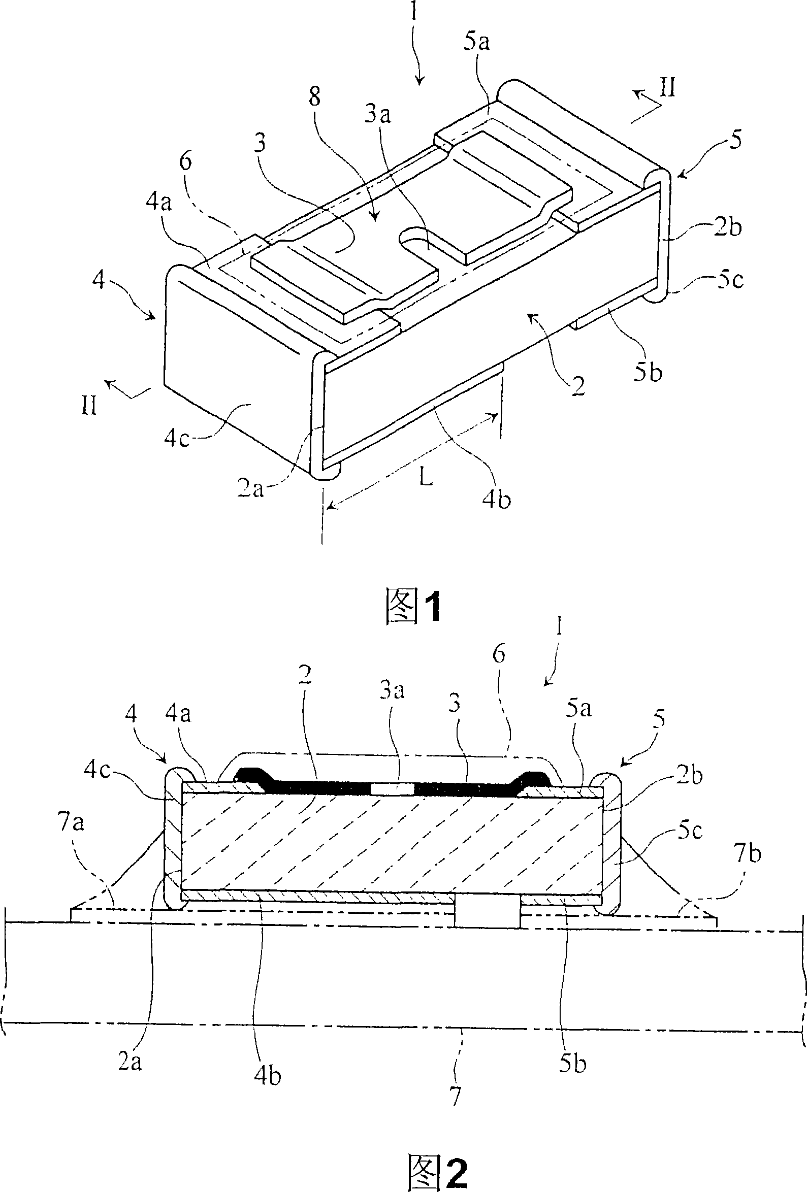
[0025] 1 and 2 are schematic diagrams showing a chip resistor 1 according to a first embodiment of the present invention.

[0026] In this chip resistor 1 , a pair of terminal electrodes 4 and 5 are provided on both ends of an insulating substrate 2 constituting a chip type (rectangular thin plate in plan view). A pair of terminal electrodes 4, 5 are formed on the upper surface of the insulating substrate 2 by upper electrodes 4a, 5a; lower electrodes 4b, 5b formed on the lower surface of the insulating substrate 2; On the upper side, the side electrodes 4c, 5c formed to conduct with the upper electrodes 4a, 5a and the lower electrodes 4b, 5b are formed.

[0027] On the upper surface of the insulating substrate 2 , a resistive film 3 is formed to extend...


PUM


Abstract

The present invention provides a chip resistor (1), comprising: a pair of terminal electrodes (4, 5) provided at the ends of an insulating substrate (2) constituting a chip shape; On the upper side, a resistive film (3) is formed in such a manner as to conduct with a pair of terminal electrodes (4, 5), and an adjustment groove (3a) for setting a resistance value is formed on a part thereof. The pair of terminal electrodes (4, 5) includes a lower electrode (4b) formed on the lower surface of the insulating substrate (2), and the lower electrode (4b) extends to the adjustment groove (3a) formed on a part of the resistance film (3). And the position directly below the narrow portion (8) that makes the width dimension of the resistive film (3) narrow.

Description

technical field [0001] The present invention relates to a chip resistor in which a resistive film is formed on the surface of a chip-shaped insulating substrate. Background technique [0002] Conventionally, as described in Patent Document 1, such a chip resistor has a pair of terminal electrodes provided on both ends of an insulating substrate constituting a chip shape. A resistive film is formed on the upper surface of the insulating substrate so as to extend along both ends of the insulating substrate. [0003] Patent Document 1: Japanese Patent Application Laid-Open No. 8-213202. [0004] The terminal electrodes consist of an upper electrode formed on the upper surface of the insulating substrate in electrical conduction with the resistive film, a lower electrode formed on the lower surface of the insulating substrate, and a connection between the upper electrode and the lower electrode on the end surface of the insulating substrate. It is composed of side electrodes f...

Claims


Application Information

Patent Timeline
IPC IPC(8): H01C7/00H01C1/142H01C1/084H01C17/242
Inventor 塚田虎之
Owner ROHM CO LTD
Why Eureka
Try Eureka