Mobile medical ventilator

一种驱动泵、呼气阀的技术,应用在呼吸器、其他医疗器械、药物的器械等方向,能够解决高压泵固有局限性影响、降低系统可移动性等问题,达到快速响应时间、增加可伸缩性、节约电力的效果

Inactive Publication Date: 2008-08-20
GENERAL ELECTRIC CO
View PDF2 Cites 7 Cited by
  • Summary
  • Abstract
  • Description
  • Claims
  • Application Information

AI Technical Summary

Problems solved by technology

Vent systems integrated with high-pressure pumps used to pressurize ambient air suffer from inherent limitations of high-pressure pumps
Generally, high pressure pumps suffer from the fact that they are relatively large and heavy, which reduces the mobility of the systems in which they are used

Method used


Image

  • Mobile medical ventilator
  • Mobile medical ventilator
  • Mobile medical ventilator

Examples


Embodiment Construction

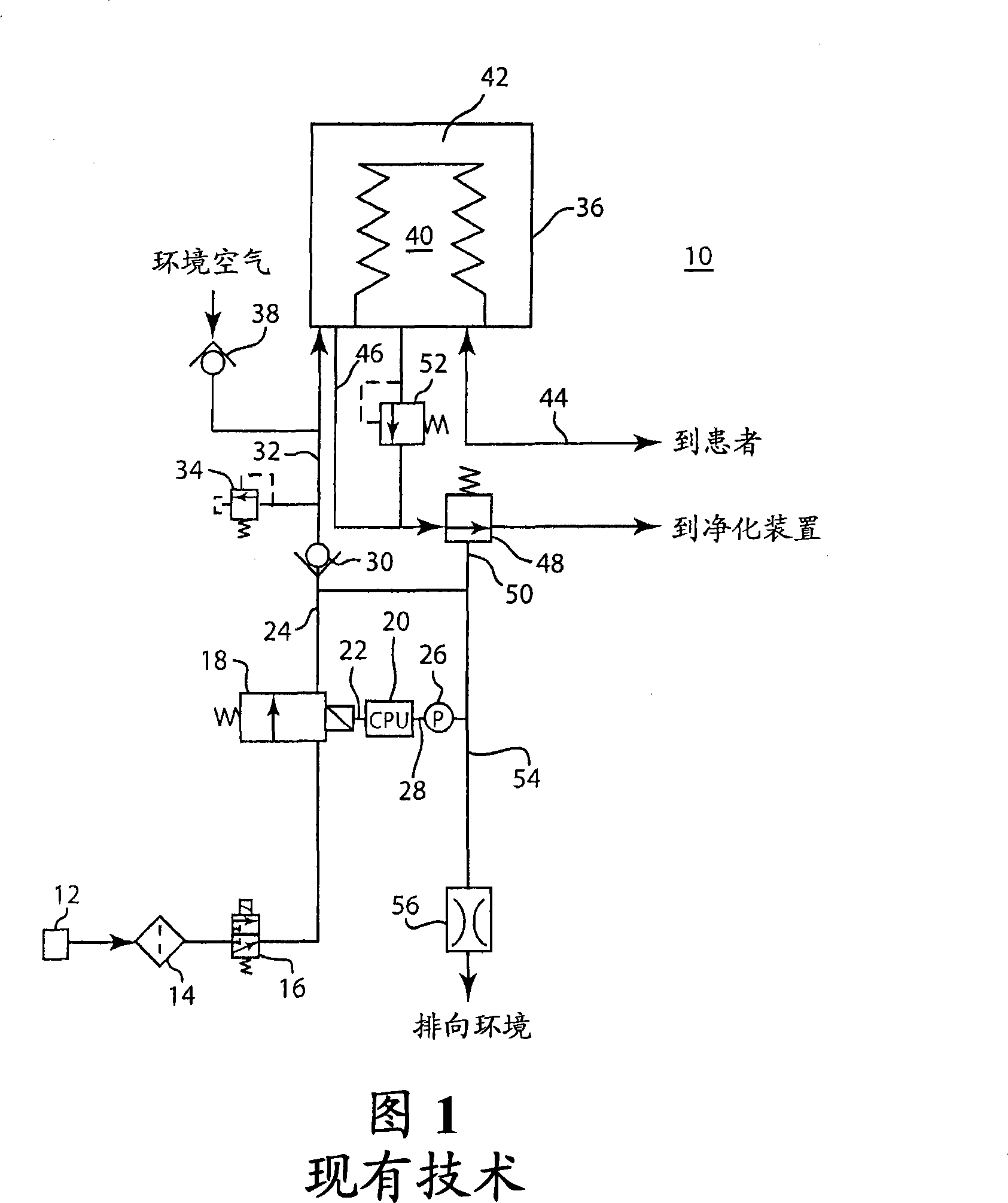
[0024] FIG. 1 depicts a schematic diagram of an aeration system 10 known in the art. A ventilator in such a system is described in US Patent No. 5,315,989 to Tobia, which is hereby incorporated by reference in its entirety. In the ventilation system 10 , a pressurized source 12 of medical gas is connected to a regulator 14 and a gas inlet valve 16 . Pressurized medical gas is used as the driving gas to operate the ventilation system 10 . Pressurized gas flows from inlet valve 16 to inspiratory flow control valve 18 . Typically, the inspiratory flow control valve 18 is a proportional flow solenoid valve, but many other suitable types of valves exist, including single pulse width or multiple pulse width modulated (PWM) two position valves. The inspiratory flow control valve 18 is controlled by a CPU 20 via a line 22 . The CPU 20 directs the inspiratory flow control valve 18 to open and close according to the desired pressure in the first inspiratory conduit 24 . The pressure...


PUM


Abstract

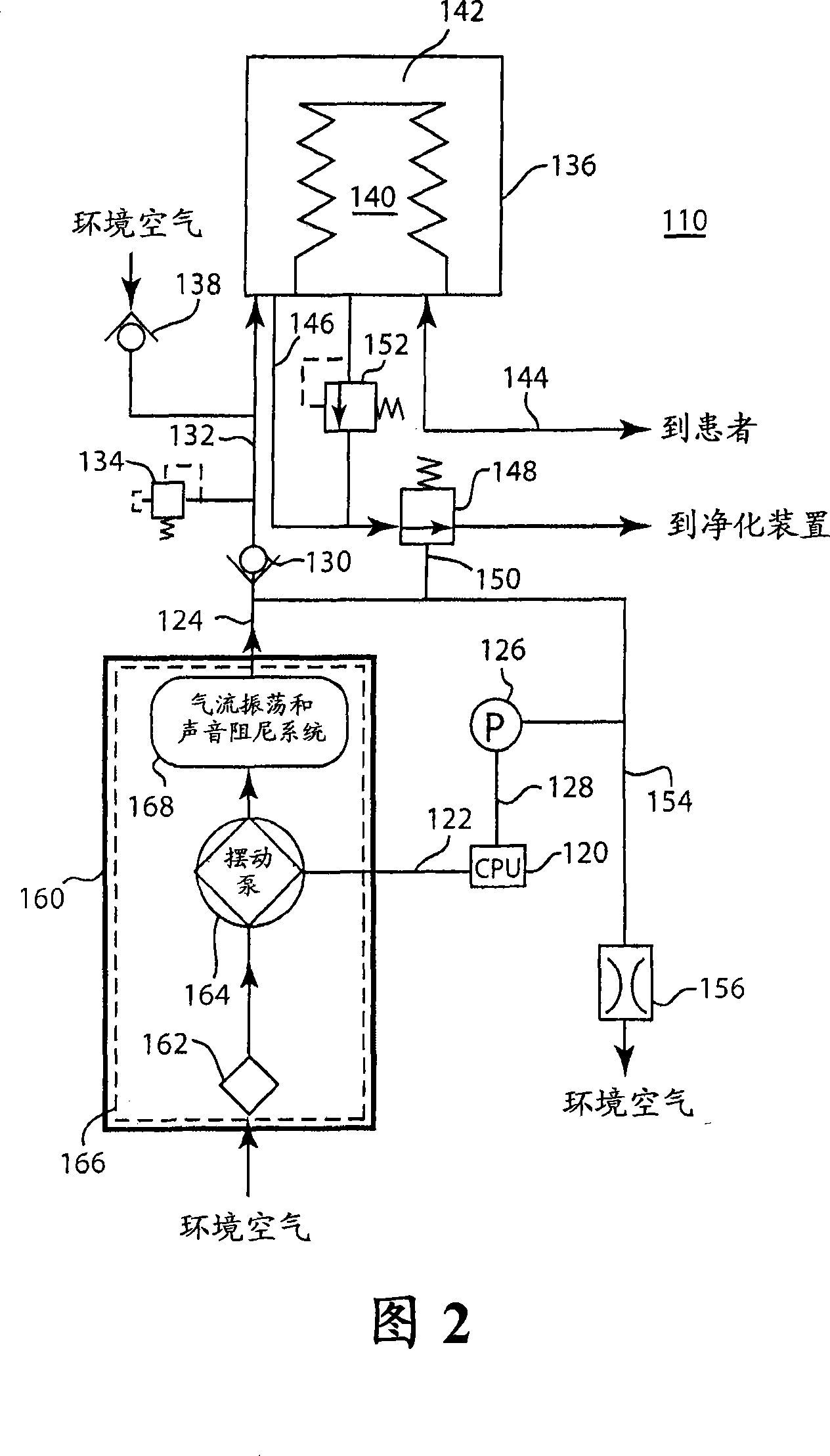
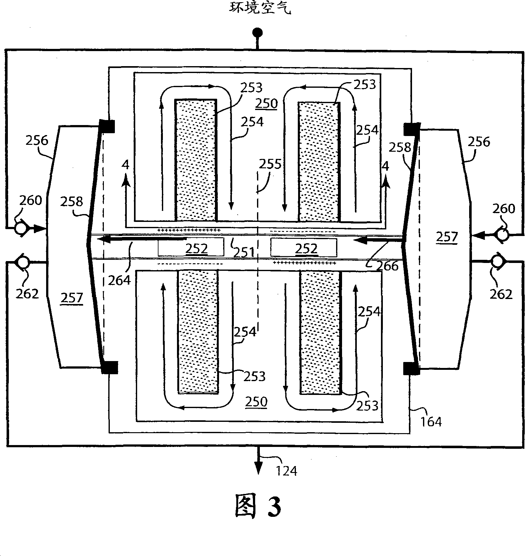
A ventilatory system for providing ventilatory support to a patient without the need for an external source of pressurized drive gas. The ventilatory system comprises a drive pump and a controller such that the drive pump collects ambient air and may pressurize it to a pressure determined by the controller. The controller may signal to the drive pump to pressurize the collected ambient air to a first pressure for delivering ventilatory support to a patient and a second pressure for providing PEEP support to a patient. The controller may signal to the drive pump to deliver a targeted flow and / or volume of collected ambient air to the bellows to provide volumetric ventilatory support during inhalation and a PEEP support during exhalation.

Description

technical field [0001] The present invention relates to a mechanical ventilator for providing respiratory support to a patient, including delivery of anesthesia and ventilatory support. In particular, the present invention relates to mechanical ventilators with improved mobility. Background technique [0002] Patients with breathing difficulties often must be placed on a mechanical ventilator. These dyspnoeas may be pathological in nature, or may result from the fact that the patient is too weak or overly sedated to perform the respiratory function independently. Patients may frequently attempt to breathe spontaneously but are unable to complete a full breathing cycle. In these cases, mechanically assisted ventilation was provided. In some mechanically assisted ventilation platforms, a combination of pressure and / or flow sensors detects the patient's breathing attempts. The detection of a breath attempt triggers the mechanical delivery of breaths. This breathing is prov...

Claims


Application Information

Patent Timeline
Patent Type & Authority Applications(China)
IPC IPC(8): A61M16/00A61M16/01
CPCA61M2016/0039A61M16/0081A61M2016/0027A61M16/0075A61M16/0057A61M16/00A61M2205/42A61M2016/0081A61M16/0063A61M16/107A61M16/024
Inventor P·J·科尔迈尔S·I·库特科R·塔姆N·里克J·L·伍兹
Owner GENERAL ELECTRIC CO
Why Eureka
Try Eureka