Linear electric motor driven numerical control machine functional module

A linear motor and functional module technology, which is applied in driving devices, metal processing mechanical parts, metal processing equipment, etc., can solve the problems of large mechanical inertia, large mechanical assembly, and low dynamic performance, and achieve small mechanical inertia and high rigidity. , the effect of good dynamic performance

Inactive Publication Date: 2008-08-20
BEIHANG UNIV
View PDF0 Cites 4 Cited by
  • Summary
  • Abstract
  • Description
  • Claims
  • Application Information

AI Technical Summary

Problems solved by technology

Such a design often has a large mechanical assembly and a large mechanical inertia, which a

Method used


Image

  • Linear electric motor driven numerical control machine functional module
  • Linear electric motor driven numerical control machine functional module
  • Linear electric motor driven numerical control machine functional module

Examples


Embodiment 1

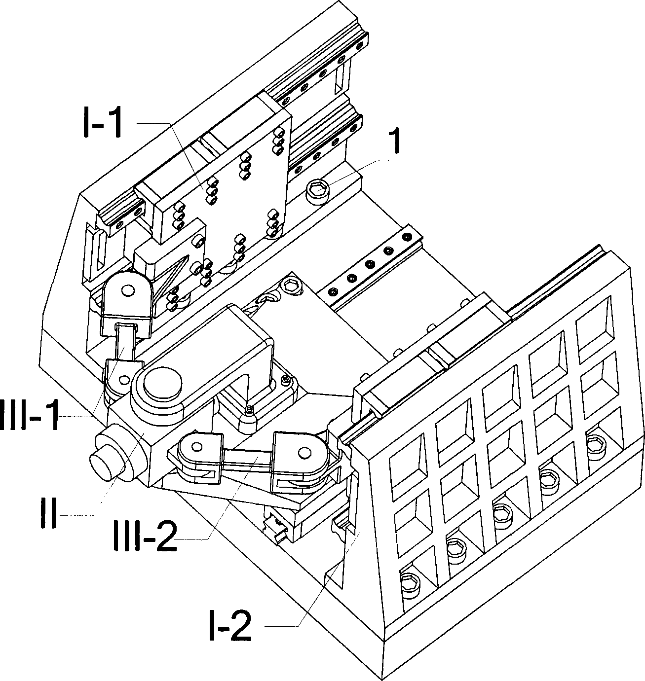
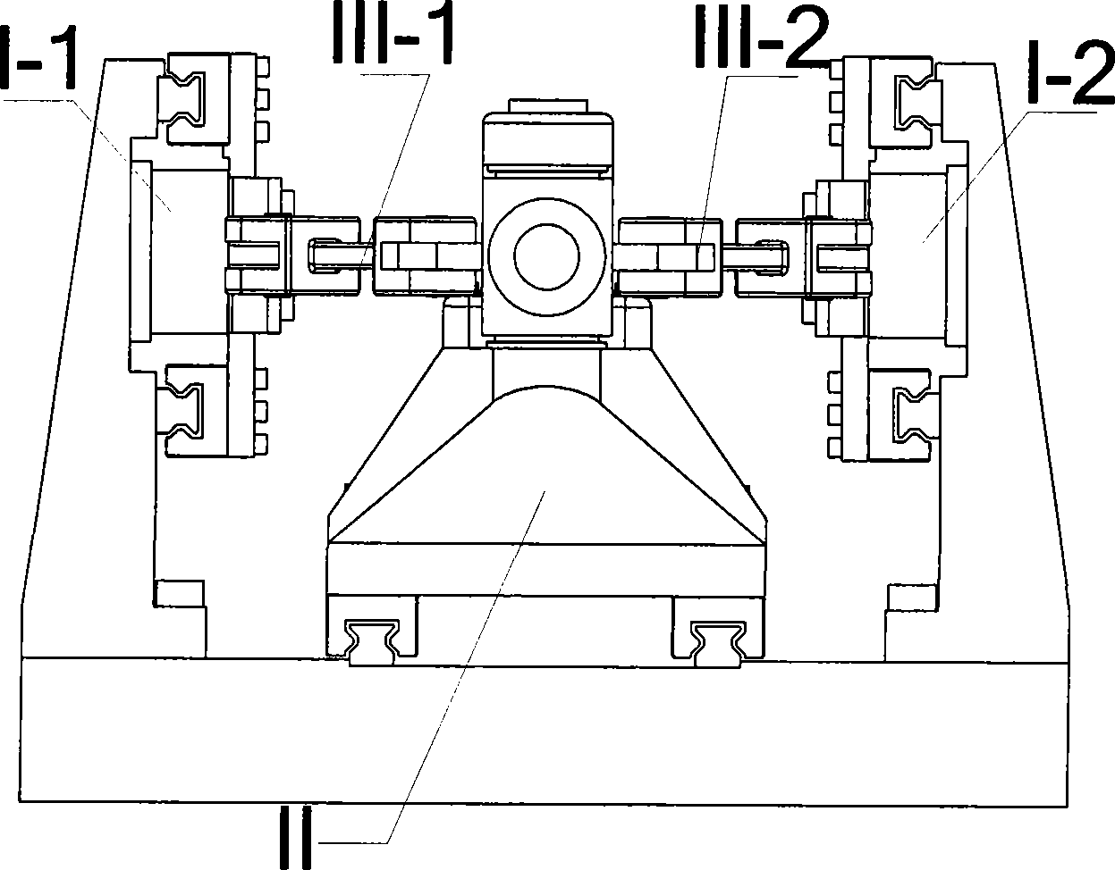
[0050] The linear motor-driven CNC machine tool functional modules include two sets of linear drive modules I-1, I-2, one tool platform movement module II, and two sets of connecting rod components III-1, III-2. The linear motions of the two linear drive modules I-1 and I-2 are the motion input of the present invention, and the tool platform 16 in the tool platform motion module II has two degrees of freedom, one linear motion and one rotary motion, which are the motions of the present invention output. It is characterized by:

[0051] Such as figure 1 , figure 2 , Figure 4 As shown, the functional module of the CNC machine tool driven by the linear motor is a symmetrical structure, which is symmetrical about the linear motion axis of the tool platform 16; the linear drive modules I-1 and I-2 are respectively arranged on the sides of the tool platform motion module II. Both sides are respectively connected with the tool platform motion module II through connecting rod co...

Embodiment 2

[0059] Embodiment 2 of the present invention is similar to Embodiment 1, including two sets of linear drive modules I-1', I-2', one tool platform movement module II', two sets of connecting rod components III-1', III-2 '. The two linear drive modules I-1', I-2' and the two groups of connecting rod parts III-1', III-2' are the same as those in the first embodiment. The difference is the implementation of the tool platform motion module II'.

[0060] Such as Figure 9 , Figure 10 , Figure 11 As shown, the tool platform movement module II' is composed of U-shaped seat 29, top cover 30, platform connecting rod 31, platform slider B 32, platform guide rail B 33, tool platform B 36, etc., the tool platform movement module II' is a vertically symmetrical structure. The U-shaped seat 29 is a combination of the motor seat 2 and the base 9 in the first embodiment into one part to complete the installation of the stator of the linear motor and the installation of the platform guid...


PUM


Abstract

The invention relates to a function module of the NC machine tool driven by a linear motor, which is characterized in that: the invention comprises two groups of linear driving modules, a moving module of the cutter platform, two groups of connecting rod parts; the function module is a symmetrical structure of the linear moving axis of the cutter platform; the linear driving modules are respectively arranged at two sides of the moving module of the cutter platform, and are respectively connected with the moving module of the cutter platform by the connecting rod parts; each group of the linear driving module is a linear feeding module driven by the linear motor, and the linear moving axis is in parallel to the linear moving axis of the moving module of the cutter platform. The NC machine tool function module has the advantages of adopting parallel driving of the double linear motor, achieving the linear movement and deflecting movement of the cutter platform, good dynamic performance, small mechanical inertia and big rigidity.

Description

【Technical field】 [0001] The invention relates to a functional module of a numerically controlled machine tool driven by a linear motor, in particular to a functional module of a two-axis numerically controlled machine tool. It belongs to the field of numerical control machine tools. 【Background technique】 [0002] The machine tool industry is the basic industry for the development of the national economy and the top priority for the development of the equipment manufacturing industry. It can be said that without the machine tool industry, there will be no other industries. [0003] The machine tool is composed of various functional components, that is, functional modules (spindle unit and spindle head, ball screw pair, rotary table, CNC servo system, etc.) It is an important part of CNC machine tools. The main task of CNC machine tool main engine factory is to manufacture basic components such as bed and column, and assemble the required functional components with them in...

Claims


Application Information

Patent Timeline
IPC IPC(8): B23Q5/02B23Q5/22
Inventor 刘强吴文镜
Owner BEIHANG UNIV
Why Eureka
Try Eureka