
Grinding device and grinder using the same

A grinding and moving device technology, applied in grinding machines, optical surface grinders, grinding/polishing equipment, etc., can solve problems such as affecting the use of grinding machines, affecting the sealing effect, and deviation of roller blinds, so as to improve processing efficiency and reduce Labyrinth gap, the effect of improving sealing performance

Active Publication Date: 2008-08-20
陈耀龙
View PDF3 Cites 11 Cited by
  • Summary
  • Abstract
  • Description
  • Claims
  • Application Information

AI Technical Summary

Problems solved by technology

However, because the working medium is very corrosive to the mechanical parts, it is necessary to provide a fully enclosed protection for the grinding machine.
There are two popular protective devices: one is roller shutter protection, the protective material of which is high-strength waterproof fabric, and it must be adjusted accurately before use so that the axis of the roller shutter is absolutely perpendicular to the moving direction, otherwise, if there is a slight inclination, it will It will cause the roller blind to deviate and affect the sealing effect; the second is the labyrinth protection, the protective material is metal plate plus coating, that is, sheet metal, so it is required to have a large gap during use, otherwise, the gap is too small , easy to produce scratches between sheet metal parts; in addition, after a period of use, the coating may fall off, resulting in blockage of relevant pipes and media channels, and ultimately affect the use of the grinder
[0013] It can be seen that the grinding device in the prior art has low machining accuracy, low production efficiency, or high production cost; correspondingly, the grinding machine in the prior art also has low machining accuracy and low production efficiency. Low, poor protective measures, high production costs
However, the prior art is limited to solving the above-mentioned problems in a certain aspect, and does not propose a whole set of solutions

Method used


Image

  • Grinding device and grinder using the same
  • Grinding device and grinder using the same
  • Grinding device and grinder using the same

Examples


Embodiment Construction

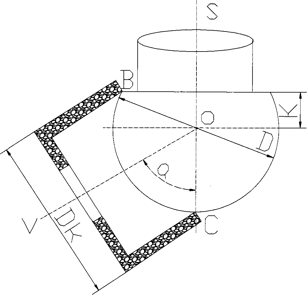
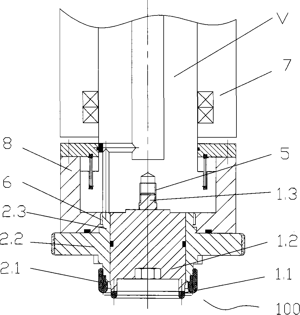
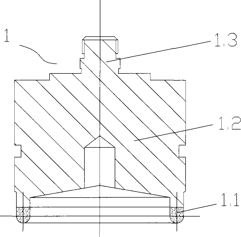
[0074] The basic idea of ​​the present invention is: the grinding device is equipped with two mutually independent grinding wheels on the grinding wheel shaft, which are respectively an outer grinding wheel and an inner grinding wheel, wherein the inner grinding wheel is fixed on the rotating shaft of the grinding wheel shaft for fine grinding; the outer grinding wheel It can move axially along the grinding wheel shaft for coarse grinding; the grinding machine uses the above grinding device, the swing shaft is driven by a torque motor, the stator of the motor is fixed to the shell of the swing shaft, and the rotor of the motor is directly installed on the shaft of the swing shaft , and the swing shaft is directly connected with the grinding wheel shaft; further, the protective cover adopts a labyrinth protective structure, and its movable parts are made of corrosion-resistant materials through cutting.

[0075] The specific implementation manners of the present invention will b...


PUM


Abstract

The invention discloses a grinding device, comprising a bowl-shape outer grinding wheel, a bowl-shape inner grinding wheel and a grinding wheel shaft, which is characterized in that: the outer grinding wheel is sleeved on the inner grinding wheel; two mutually independent grinding wheel positioning interfaces are arranged on the grinding wheel shaft, which are used to arranged the outer grinding wheel and the inner grinding wheel; the inner grinding wheel is fixed on the grinding wheel shaft to do fine grinding to the workpiece; the outer grinding wheel can move up on the shaft of the grinding wheel shaft to do coarse grinding to the workpiece. The grinding device has advantages that: the processing precision is improved; the abrasion of the grinding wheel is reduced; and the production efficiency is increased. The invention also discloses a grinder which uses the grinding device.

Description

technical field [0001] The invention relates to the field of mechanical manufacturing, in particular to a grinding device and a grinding machine using the grinding device, which are particularly suitable for use in cold processing of optical elements. Background technique [0002] Grinding is to use abrasives to cut the surface of the workpiece, which is one of the important methods of parts processing. The most important tool in grinding is the grinding wheel, which consists of three elements: abrasive grains, bond and voids. With the difference of abrasive grains, bonding agent and grinding wheel manufacturing process, the characteristics of grinding wheel may vary greatly, which has an important impact on the precision and production efficiency of grinding processing. In order to meet the requirements of machining accuracy, it is often necessary to dress the grinding wheel, especially when it is worn out, it must be replaced. In addition, in some grinding wheels, it is ...

Claims


Application Information

Patent Timeline
IPC IPC(8): B24B13/01
Inventor 陈耀龙
Owner 陈耀龙
Learn More