Polymer optical fiber prefabricated stick drafting device

An optical fiber preform and stretching device technology, applied in optical components, comprehensive factory control, electrical program control, etc., can solve the problems of large optical fiber loss, low tower body, backward polymer optical fiber technology, etc. The effect of high fiber yield

Inactive Publication Date: 2008-08-20
XI'AN INST OF OPTICS & FINE MECHANICS - CHINESE ACAD OF SCI
View PDF0 Cites 6 Cited by
  • Summary
  • Abstract
  • Description
  • Claims
  • Application Information

AI Technical Summary

Problems solved by technology

[0002] my country's polymer optical fiber technology is backward. The existing polymer optical fiber manufacturing equipment has a low tower body and a simple drawing furnace structure. Generally, it can only draw thinner and shorter preforms, and the preforms are not h

Method used


Image

  • Polymer optical fiber prefabricated stick drafting device
  • Polymer optical fiber prefabricated stick drafting device
  • Polymer optical fiber prefabricated stick drafting device

Examples


Embodiment Construction

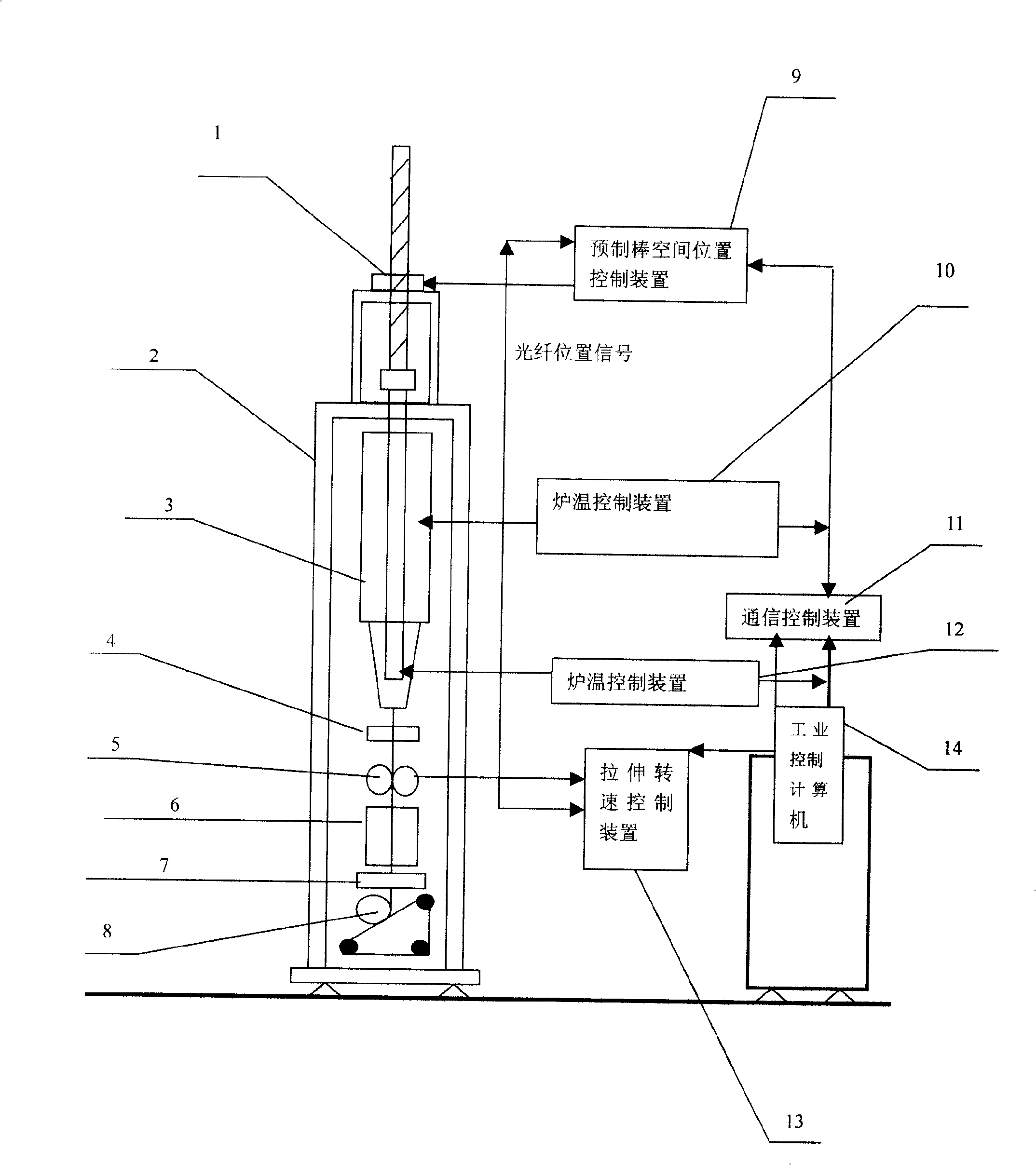
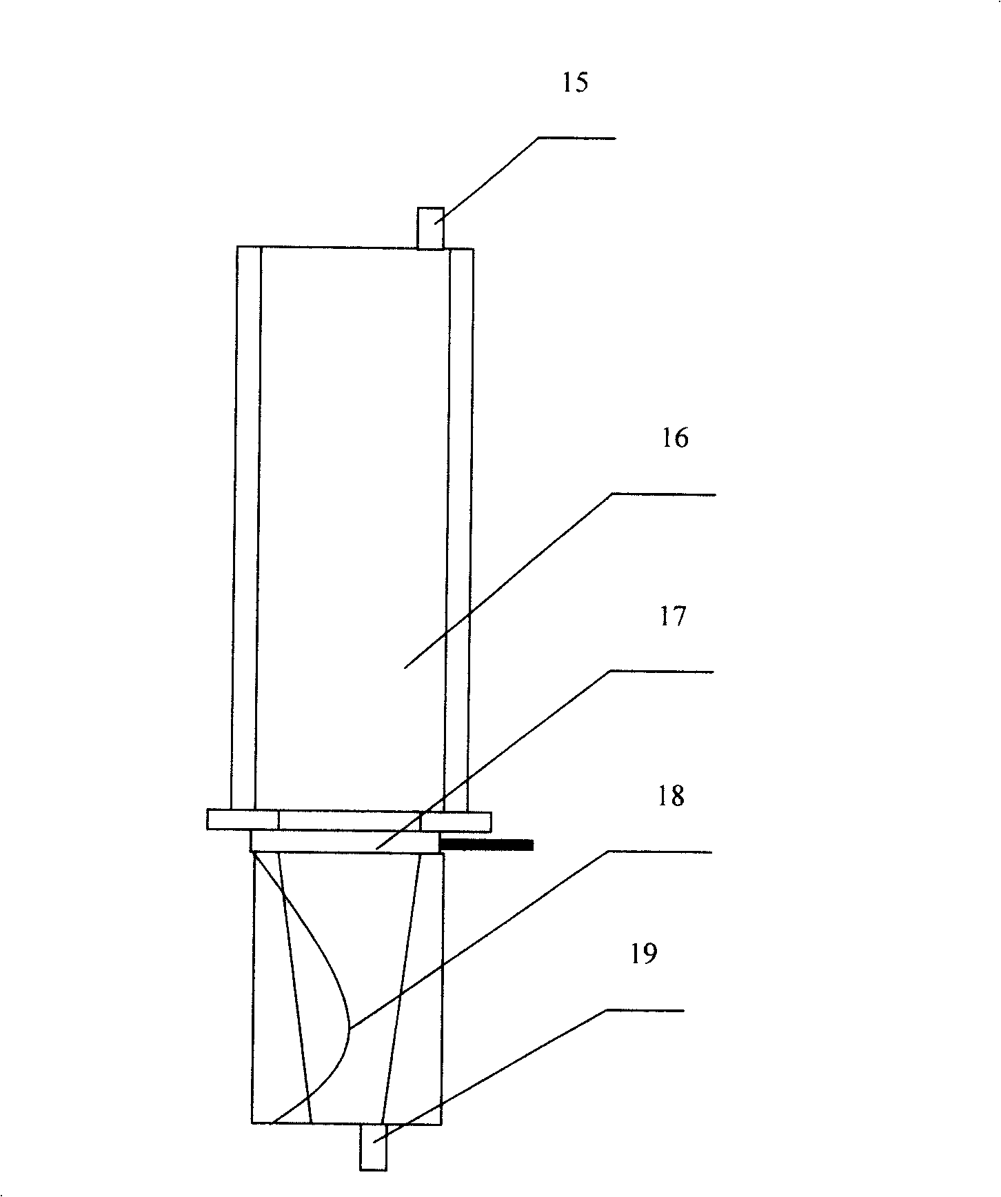
[0018] see figure 1 , the present invention includes a tower 2 and a preform feeding device 1 arranged on the tower, a heating and stretching furnace 3, a caliper 4, a main traction device 5, an annealing furnace 6, a coating layer device 7, and a wire receiving device 8. The preform feeding device 1 is arranged above the heating and stretching furnace 3, the diameter measuring instrument 4 is arranged under the heating and stretching furnace 3, the main traction device 5 is arranged under the diameter measuring instrument 4, and the annealing furnace 6 is arranged under the main traction device 5, A coating layer device 7 is arranged below the annealing furnace 6, and a wire collecting device 8 is arranged below the coating layer device 7. The heating and stretching furnace 3 includes a preform stretching zone 16 and a preform softening zone 18, and the preform stretching zone 16 It is arranged above the softening zone 18 of the preform rod.

[0019] The caliper 4 adopts a l...


PUM


Abstract

The invention relates to a polymer optical fiber preform stretching device, which adopts technical proposal that: the device comprises a tower frame, and a preform feed device, a heating stretching furnace, a diameter-measuring instrument, a main traction device, an annealing oven, a coating device and a fiber rolling device that are arranged on the tower frame, wherein the preform feeding device is arranged above the heating stretching furnace, the diameter-measuring instrument is arranged below the heating stretching furnace, the main traction device is arranged below the diameter-measuring instrument, the fiber rolling device is arranged below the coating device, the heating stretching furnace comprises a preform stretching area and a preform softening area, the preform stretching area is arranged above the preform softening area. The stretching device has the advantages of high yield and large-scale industrial production.

Description

technical field [0001] The invention relates to a stretching device for a polymer optical fiber preform rod. Background technique [0002] my country's polymer optical fiber technology is backward. The existing polymer optical fiber manufacturing equipment has a low tower body and a simple drawing furnace structure. Generally, it can only draw thinner and shorter preforms, and the preforms are not heated uniformly in the drawing tower. As a result, the filament diameter of the polymer optical fiber is inconsistent, and the loss of the optical fiber is large, which cannot meet the requirements of large-scale production of low-loss and high-bandwidth optical fibers. Contents of the invention [0003] The key to the large-scale production of polymer optical fibers is the manufacture of high-quality preforms and high-precision preform drawing towers. The invention solves the technical problem of low-quality drawing polymer optical fiber in the polymer optical fiber drawing equ...

Claims


Application Information

Patent Timeline
IPC IPC(8): B29D11/00G05B19/418
Inventor 王丽莉陈兴华赵卫
Owner XI'AN INST OF OPTICS & FINE MECHANICS - CHINESE ACAD OF SCI
Why Eureka
Try Eureka