Method for antilocking for shuttle operation of three-dimensional textile machine

A three-dimensional knitting machine and knitting machine technology, which is applied in the directions of twisting lace looms, woven fabrics, textiles and paper making, etc. problems, to achieve the effect of smooth operation, simple structure and convenient maintenance.

Inactive Publication Date: 2008-08-20
CHANGZHOU BOLONG THREE DIMENSIONAL COMPOSITES
View PDF0 Cites 7 Cited by
  • Summary
  • Abstract
  • Description
  • Claims
  • Application Information

AI Technical Summary

Problems solved by technology

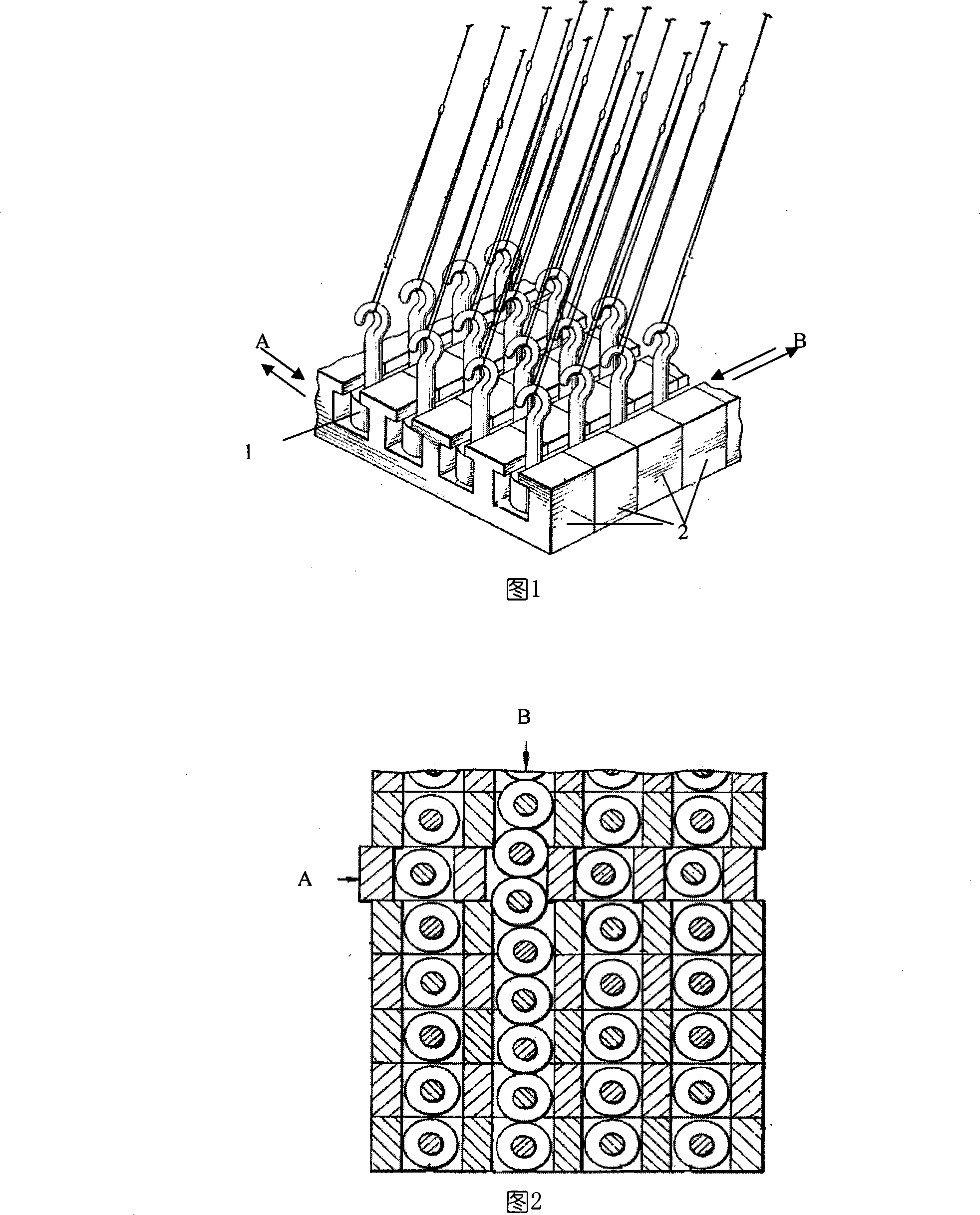
Figure 2 shows the result of running operation that is often produced in practice: after each step of running in direction A, the shuttle box 2 and the shuttle 1 therein cannot ensure that each row or column is accurately arranged as a "row" and "column" In this way, the operation in the direction B will not be smooth in the future, and the phenomenon of "stuck" will easily occur, that is, it is easy to cause some shuttles 1 to be stuck due to the inappropriate movement along the "soil" shaped groove. Between two rows of shuttle boxes 2

Method used


Image

  • Method for antilocking for shuttle operation of three-dimensional textile machine
  • Method for antilocking for shuttle operation of three-dimensional textile machine

Examples


Embodiment

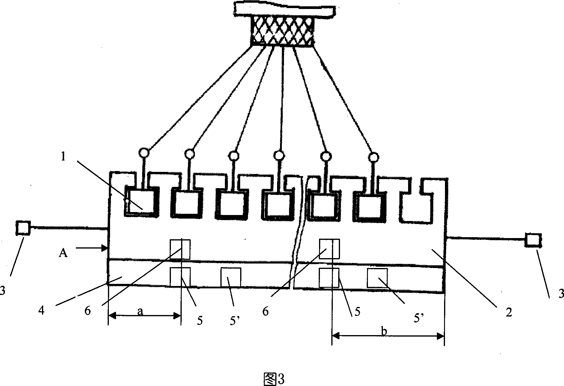
[0016] In the embodiment shown in Figure 3: the shuttle 1 is placed in the groove of each shuttle box 2, and can be controlled to slide back and forth in the direction B along the groove of the shuttle box 2, and each shuttle box 2 arranged side by side on the machine bracket It can slide back and forth in the direction A under the promotion of the respective shuttle box push rods 3, so that each shuttle 1 can move up, down, left, and right in the four-step knitting. Two cylindrical sintered NdFeB magnets are embedded in the lower plane of each shuttle box 2, which are called shuttle box magnets 6 in the present invention. The diameter of these two cylindrical magnets is 10 mm, the height is 10 mm, and the magnetic pole N faces downward, and they are respectively arranged at the left and right ends of the shuttle box. The specific position is that the distance a from the left end is 100 mm, The distance b from the right end is 115 mm. And in the upper plane position of the sh...


PUM


Abstract

A method of the anti-blocking of the operation of the shuttle of a three dimensional fabric knitting machine arranges the shuttle in the slot of a shuttle box and the shuttle can be controlled to slide to and fro along the slot of the shuttle box; while the shuttle box can slide to and fro under the pushing of a shuttle box push bar; at the moment, a tiny transmission intermission exists between the shuttle box push bar and the shuttle box during design and mounting; besides, the lower plane part of each shuttle box is internally embedded with a plurality of shuttle box magnets arrayed in certain distance; while the upper plane parts of the bases of the shuttle boxes corresponding to the position of each shuttle box magnet is internally embedded with A-position magnets of the bases of the shuttle boxes with the same quantity; B-position magnets of the bases of the shuttle boxes with the same quantity are also embedded at the position which is one traverse step length to the A-position magnets of the bases of the shuttle boxes. The poles of the A-position magnets of the bases of the shuttle boxes and the B-position magnets of the bases of the shuttle boxes are collocated with the magnets of the shuttle boxes to form an 'opposite attraction' state to finish the automatic accurate contraposition of the shuttle boxes in A-position and B-position by the mutual attraction. Consequently, during the operation of the knitting machine, each push bar of the shuttle box pushes corresponding shuttle box in a not very accurate and in place mode; while the accurate position is automatically adjusted and reached by the opposite attraction of the shuttle box magnets to the magnets of the bases of the shuttle boxes, thus improving the operation state of the knitting machine to lead the knitting machine to be well-off and accurate.

Description

Technical field [0001] The invention relates to a technology of a three-dimensional fabric knitting machine, in particular to a technology for preventing jamming of a shuttle of the three-dimensional fabric knitting machine. Background technique [0002] Three-dimensional woven fabric is a high-tech product that is being researched and developed at home and abroad in recent years. It is mainly used as a prefabricated part of special-shaped composite materials. The use performance of cracking, as a new material for key parts in military industry, national defense, aerospace and civil special fields, is getting more and more attention. [0003] The three-dimensional fabric weaving machine is the core processing equipment of this high-tech product. In terms of weaving methods, there are two typical applications: two-step three-dimensional weaving and four-step three-dimensional weaving. Among them, four-step three-dimensional weaving is widely used at present. For the conven...

Claims


Application Information

Patent Timeline
Patent Type & Authority Applications(China)
IPC IPC(8): D04C3/00D04C3/48D04C5/00D04C5/26
Inventor 吴伯明周罗庆
Owner CHANGZHOU BOLONG THREE DIMENSIONAL COMPOSITES
Why Eureka
Try Eureka