Semiconductor device

A semiconductor and output terminal technology, applied in the direction of output power conversion device, DC power input conversion to DC power output, instruments, etc., can solve the problems of output voltage oscillation state, current reduction detection, current sensing circuit misoperation, etc. , to achieve the effect of suppressing overshoot and responding to load changes at high speed

Inactive Publication Date: 2008-08-20
SEIKO INSTR INC
View PDF1 Cites 19 Cited by
  • Summary
  • Abstract
  • Description
  • Claims
  • Application Information

AI Technical Summary

Problems solved by technology

[0013] However, when the load changes rapidly, a current in the opposite direction to the normal current flows in the current detection circuit 206, and the normal detection of the current decrease may not be performed, and the current sensing circuit malfunctions, for example, falling into output voltage oscillation. state

Method used


Image

  • Semiconductor device
  • Semiconductor device
  • Semiconductor device

Examples


Embodiment Construction

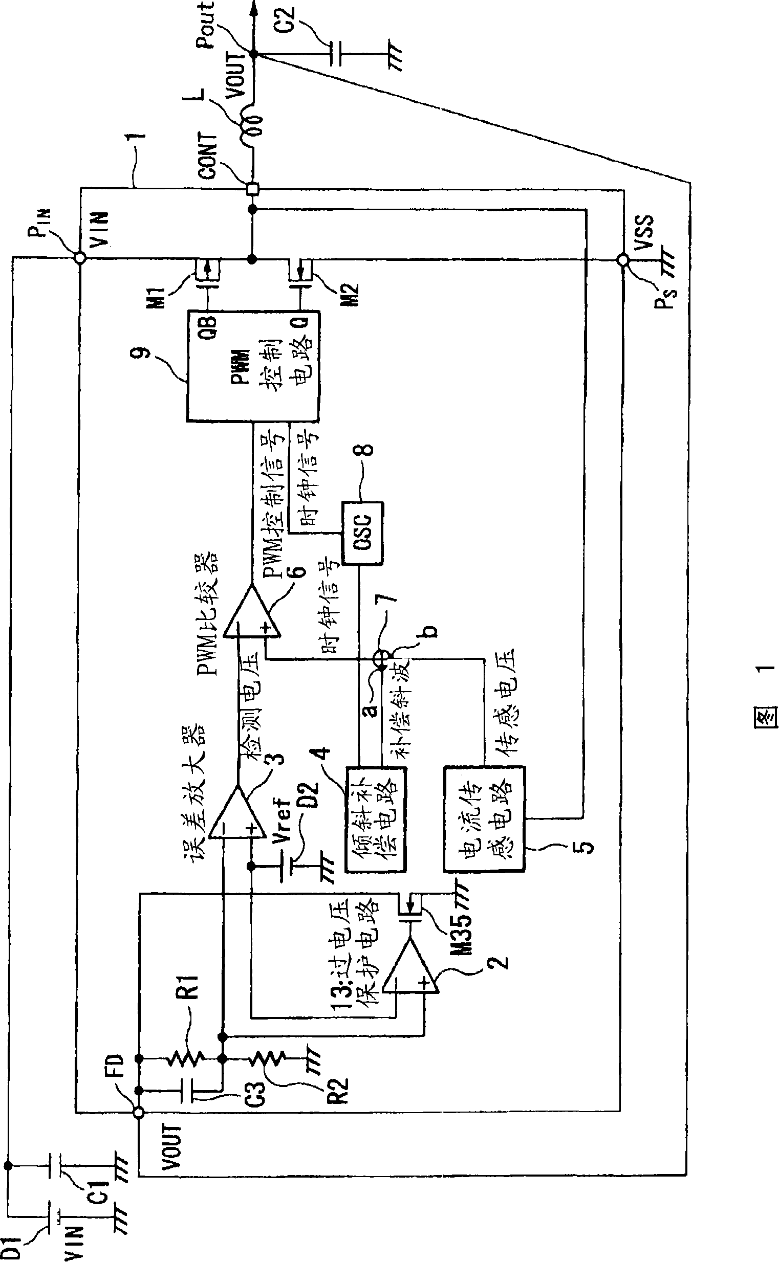
[0045] Next, a semiconductor device 1 for a current mode step-down switching regulator using an overvoltage protection circuit 13 according to an embodiment of the present invention will be described with reference to the drawings. FIG. 1 is a block diagram showing a configuration example of a step-down switching regulator according to this embodiment. The most characteristic structure of the invention of this application is the overvoltage protection circuit 13 provided to suppress the occurrence of overshoot in the output voltage Vout output from the output terminal Pout to the load when the load is suddenly reduced. The details will be described in detail.

[0046] In this FIG. 1, the current mode step-down switching regulator of this embodiment includes a semiconductor device 1 for a current mode step-down switching regulator, a coil L used for voltage conversion (step-down in this embodiment), and a pair of The smoothing capacitor C2 that smoothes the voltage output from ...


PUM


Abstract

The invention provides a switching regulator which makes the output voltage not in the oscillating state in the current way to restrain the overshoot of the output voltage in the condition of load reducing sharply. The semiconductor device of the invention converts the input DC voltage input from the DC power as the given DC output voltage and is used for the switching regulator output from the output terminal, which has a overvoltage protection protective circuit for comparing the object voltage and the output voltage on the output terminal. When the output voltage is larger than the object voltage, the output terminal is in the discharging state.

Description

technical field [0001] The present invention relates to a semiconductor device for a current mode switching regulator that uses a DC input power supply and controls an output voltage based on detected values ​​of output voltage and output current. Background technique [0002] As a current mode step-down switching regulator that inputs a DC voltage from a DC power supply and supplies an output DC voltage to a load, it is used Figure 5 A circuit having the structure shown (for example, refer to Patent Document 1). Should Figure 5 The shown current mode step-down switching regulator is composed of a switch 207, a pulse width control circuit 205, a diode 202, a capacitor 212, a coil 208, a current detection circuit 206, and a voltage detection circuit 204, and steps down the voltage input from the DC power supply 201. Vin, the output voltage after step-down is supplied to the load 209 . [0003] In this circuit, the pulse width control circuit 205 outputs a drive pulse of a ...

Claims


Application Information

Patent Timeline
Patent Type & Authority Applications(China)
IPC IPC(8): H02M3/10H02M3/156H02M1/32
CPCH02M3/158G11C5/14
Inventor 上原治
Owner SEIKO INSTR INC
Why Eureka
Try Eureka