Apparatus for reeling yarns

A winding device and yarn technology, applied in the field of yarn winding devices, can solve the problems of high cost, inaccuracy, complicated structure of the winding device, etc., and achieve the reduction of manufacturing cost and space size, and the accuracy of control. improved effect

Inactive Publication Date: 2008-08-20
SSM萨罗瑞士麦特雷有限公司
View PDF4 Cites 7 Cited by
  • Summary
  • Abstract
  • Description
  • Claims
  • Application Information

AI Technical Summary

Problems solved by technology

The disadvantage of the known winding device is that the sensor mechanism required to control the pressing force makes the structure of the winding device complicated and expensive
The measurement of compression force is also error prone and inaccurate

Method used


Image

  • Apparatus for reeling yarns
  • Apparatus for reeling yarns
  • Apparatus for reeling yarns

Examples


Embodiment Construction

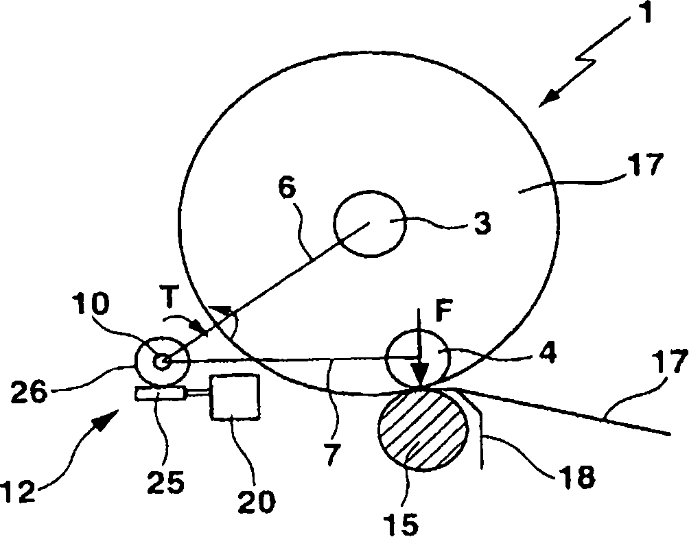
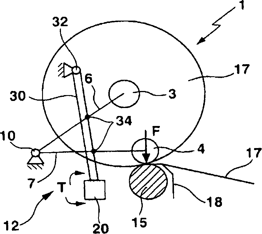
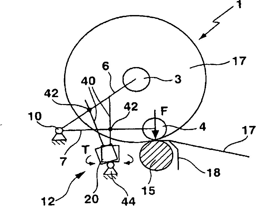
[0027] The figures represent the subject matter of the invention very schematically and are not to be understood to scale. The individual parts of the inventive subject matter are shown so that its structure is well shown.

[0028] exist Figure 1-4 In , the winding machine 1 of the invention is shown accordingly. The yarn holders 3 , 4 are arranged in yarn holder receptacles mounted rotatably about a longitudinal axis. The pressure lever arms 6 , 7 are rotatably fixed in the region of their radially inner ends at the pivot point 10 . The pressure lever arms 6 , 7 are rotatable, ie pivotable, about a pivot point 10 by means of a movable actuator 12 . The yarn holder receiver is arranged rotatably perpendicular to the pressure lever arms 6 , 7 on the outer ends of the pressure lever arms 6 , 7 . The pressure roller 15 supports the yarn holders 3, 4 arranged in the yarn holder receptacle. Thus, the compression roller 15 receives the weight of the compression lever arms 6, 7...


PUM


Abstract

Disclosed is an apparatus (1) for reeling yarn (17), comprising a bobbin receptacle that is mounted so as to be rotatable about the longitudinal axis thereof and is designed for accommodating a bobbin (3, 4), a pressure roll (15) for supporting the bobbin (3, 4) located in the bobbin receptacle, a pressure lever arm (6, 7) which is rotatably fixed to a fulcrum (10) in the region of the radially inward end thereof, and an active actuator (12) for twisting the pressure lever arm (6, 7) about the fulcrum (10). The bobbin receptacle is disposed at an outer end of the pressure lever arm (6, 7) so as to be rotatable perpendicular to the pressure lever arm (6, 7). The actuator (12) is provided with an electric motor (20) encompassing a sensorless motor controller. Said motor controller is designed so as to regulate a torque that is to be applied to the pressure lever arm (6, 7) by the electric motor (20) according to a predefined torque curve.

Description

technical field [0001] The invention relates to a device for winding yarn (winding device), which has a yarn support receiver rotatably supported about its longitudinal axis, which is provided for mounting Yarn support; pressure roller, pressure lever arm and movable actuator, the pressure roller is set to support a yarn support arranged in the yarn support receptacle, the pressure lever arm in its diameter Rotatably fixed in the region of the inner end on the pivot point, the actuator is arranged to rotate the compression lever arm around the pivot point, the yarn support receiver is rotatably arranged at Squeeze on the outer end of the lever arm. Such winding devices are used during the yarn production, for example for producing coils with yarn reels suitable for sequential processes, during the washing process, in particular during the rinsing process. Background technique [0002] The winding device is part of the yarn making machine. The yarn is wound on a yarn suppo...

Claims


Application Information

Patent Timeline
Patent Type & Authority Applications(China)
IPC IPC(8): B65H54/42
CPCB65H2515/34B65H54/52B65H2701/31B65H2555/25
Inventor D·马卡布鲁尼L·古布泽尔G·卡拉尔斯兰
Owner SSM萨罗瑞士麦特雷有限公司
Why Eureka
Try Eureka