Electric cooker and electric cooker steam barrel flow guiding method

A technology of electric rice cooker and steam cylinder, which is applied in the field of electric rice cooker, can solve the problems of increased manufacturing cost, low mouth-forming rate, and many parts, and achieve the effects of novel structure, simplified assembly process, and reduced production cost

Active Publication Date: 2008-08-27
PANASONIC APPLIANCES CHINA CO LTD +1
View PDF0 Cites 15 Cited by
  • Summary
  • Abstract
  • Description
  • Claims
  • Application Information

AI Technical Summary

Problems solved by technology

The disadvantages of the above structure are as follows: first, when the steam flow rate is high, the soup splashes out of the steam drum before it can be separated; second,...

Method used


Image

  • Electric cooker and electric cooker steam barrel flow guiding method

Examples


Embodiment 1

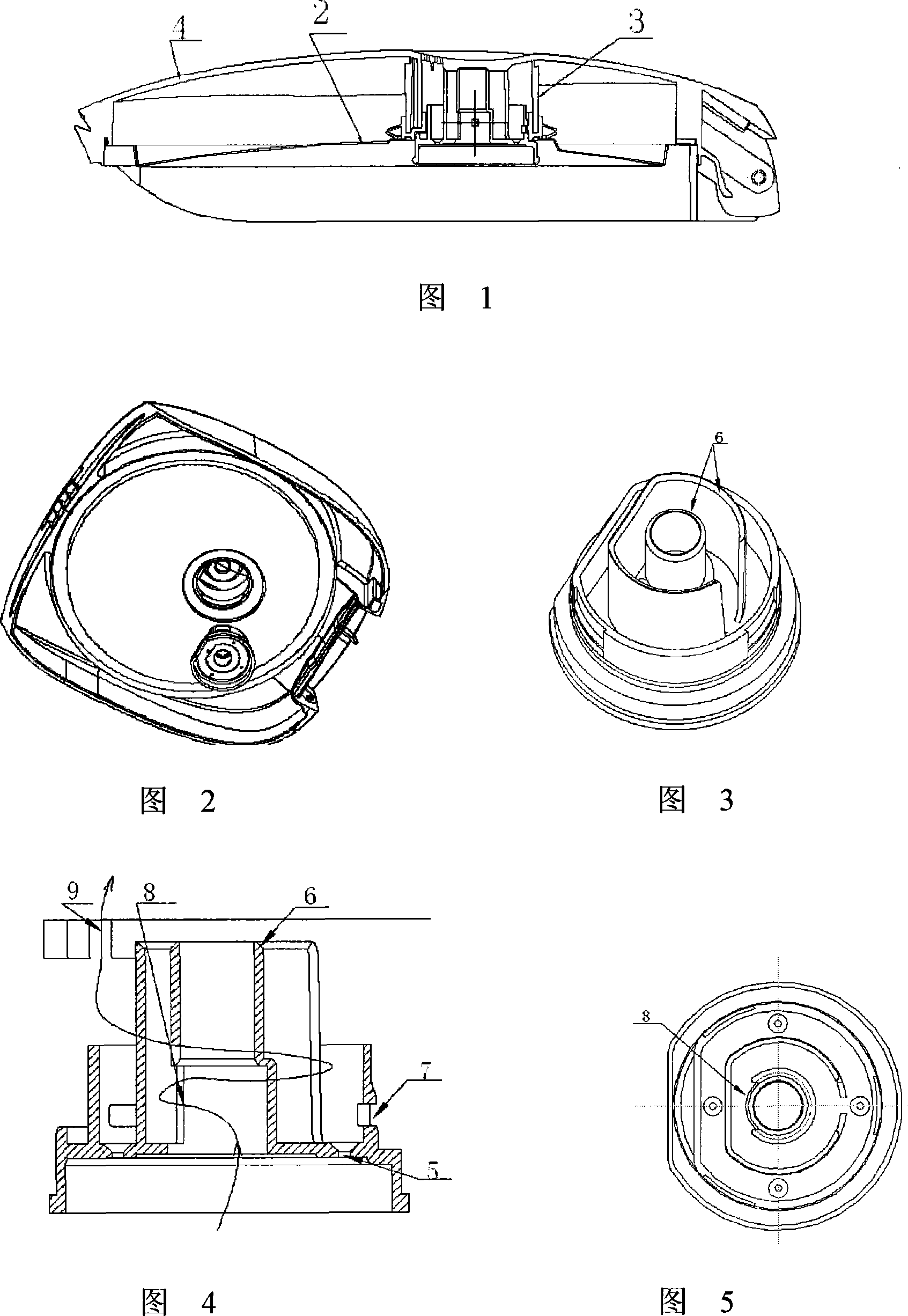
[0013] Embodiment 1: with reference to accompanying drawing 1~5. In the electric rice cooker of this embodiment, the steam drum 3 is installed in the cover of the outer cover 4 of the electric rice cooker, and the upper part of the outer cover 4 of the electric rice cooker 1 is provided with a steam drum 3 , see accompanying drawing 1 . The wall of the second steam diversion circuit in the steam cylinder 3 is provided with a steam cylinder clamping hole 7, the clamping hole 7 is clamped with the steam cylinder installation cylinder wall inside the outer cover 4, and is connected with the heat release by sealing the thermal ring 3 The plates 2 are hermetically bonded, see accompanying drawing 1 . It is located inside the outer cover 4 of the electric rice cooker 1 and the steam outlet of the steam cylinder 3 communicates with the exhaust port 9 of the outer cover. The steam outlet of the steam cylinder 3 communicates with the exhaust outlet 9 of the outer cover 4. See Figure 4...

Embodiment 2

[0015] Embodiment 2: on the basis of embodiment 1, electric rice cooker steam cylinder diversion method, it comprises electric cooker, and steam cylinder is installed in the lid of electric cooker outer cover, and steam cylinder bottom center is provided with steam pipeline and has steam on the wall of pipeline Inlet, steam and rice soup enter the first steam diversion circuit formed around the steam pipe wall from the steam inlet on the steam pipe wall, and under the action of the first steam diversion circuit wall, change the steam and The direction of the rice soup, because the opening of the first steam diversion circuit wall with the opposite steam inlet direction enters the second steam diversion circuit formed around the first steam diversion circuit wall, the steam and rice soup pass through the first steam diversion circuit During the process with the second steam diversion circuit, the flow speed of steam and rice soup decreases, and the steam and water are separated....


PUM


Abstract

The invention relates to a rice cooker and a rice cooker steam tube diversion method capable of reducing flow rate and automatically separating gas from liquid. The steam tube is positioned inside an outer cover of the rice cooker, the steam outlet port of the steam tube communicates with the exhaust port of the outer cover, a steam pipeline is arranged at the center of the bottom of the steam tube and a steam inlet port is formed on the wall of the steam pipeline, a first steam diversion loop is arranged at intervals around the wall of the steam pipeline, the outlet port of the first steam diversion loop is opposite in the direction to the steam inlet port, a second steam diversion loop is arranged at intervals around the first steam diversion loop, and the wall of the second steam diversion loop is lower than the wall of the first steam diversion loop. The inventive rice cooker has the advantages of (1) reducing pressure and speed of high-pressure rice-water mixture entering into the labyrinth diversion loops, so that the rice grains settle due to collision, thereby achieving gas-liquid separation purpose and preventing rice-water spilling over from the exhaust port of the rice cooker; and (2) simplifying the assembly process and maximally saving production cost.

Description

technical field [0001] The invention relates to an electric rice cooker and a method for diverting a steam cylinder of the electric rice cooker capable of reducing the flow rate and automatically separating vapor and liquid. Background technique [0002] The structure design of the steam tube in the existing electric cooker is that the installation position of the steam tube is on the top of the outer cover of the electric cooker, the inside of the steam guiding device provided on the cover of the electric cooker is a cavity structure, and the inside of the steam tube is provided with a cavity structure. There is a steam guide pipe that communicates with the inside of the pot body through the steam inlet hole, and a steam exhaust hole is provided on the top surface; between the steam exhaust hole and the flow guide pipe, there is a steam guide tube extending downward from the inner side of the top surface of the steam guiding device. A baffle plate; a backflow notch is provi...

Claims


Application Information

Patent Timeline
IPC IPC(8): A47J27/00A47J36/38
Inventor 杨夫健金尾修司
Owner PANASONIC APPLIANCES CHINA CO LTD
Why Eureka
Try Eureka