Hydraulic centering device

A technology of centering device and hydraulic pressure, applied in the direction of guiding/positioning/aligning device, etc., can solve the problems of reducing the quality of strip rolling, roughing of the rolls, and troublesome replacement, so as to improve the rolling efficiency, improve the rolling quality, Easy to adjust effect

Inactive Publication Date: 2008-08-27
朱惠兴
View PDF0 Cites 3 Cited by
  • Summary
  • Abstract
  • Description
  • Claims
  • Application Information

AI Technical Summary

Problems solved by technology

Although the centering of the rolled strip can be achieved by setting iron plugs on the racks at both ends of the work rolls of the rolling mill, but because the iron plugs are fixed, it is easy to cause roughening on both sides of the rolled strip
Once the strip is roughened, it will also cause the roll to be roughened.
Therefore, the use of setting iron blocks for centering will reduce the rolling quality of the strip
In addition, since the plug iron blocks are fixed on the racks at both ends of the work rolls of the rolling mill, when rolling strips of different specifications, it is necessary to stop the machine to replace the plug iron blocks, which is not only troublesome to replace, but also affects the rolling efficiency

Method used


Image

  • Hydraulic centering device

Examples


Embodiment Construction

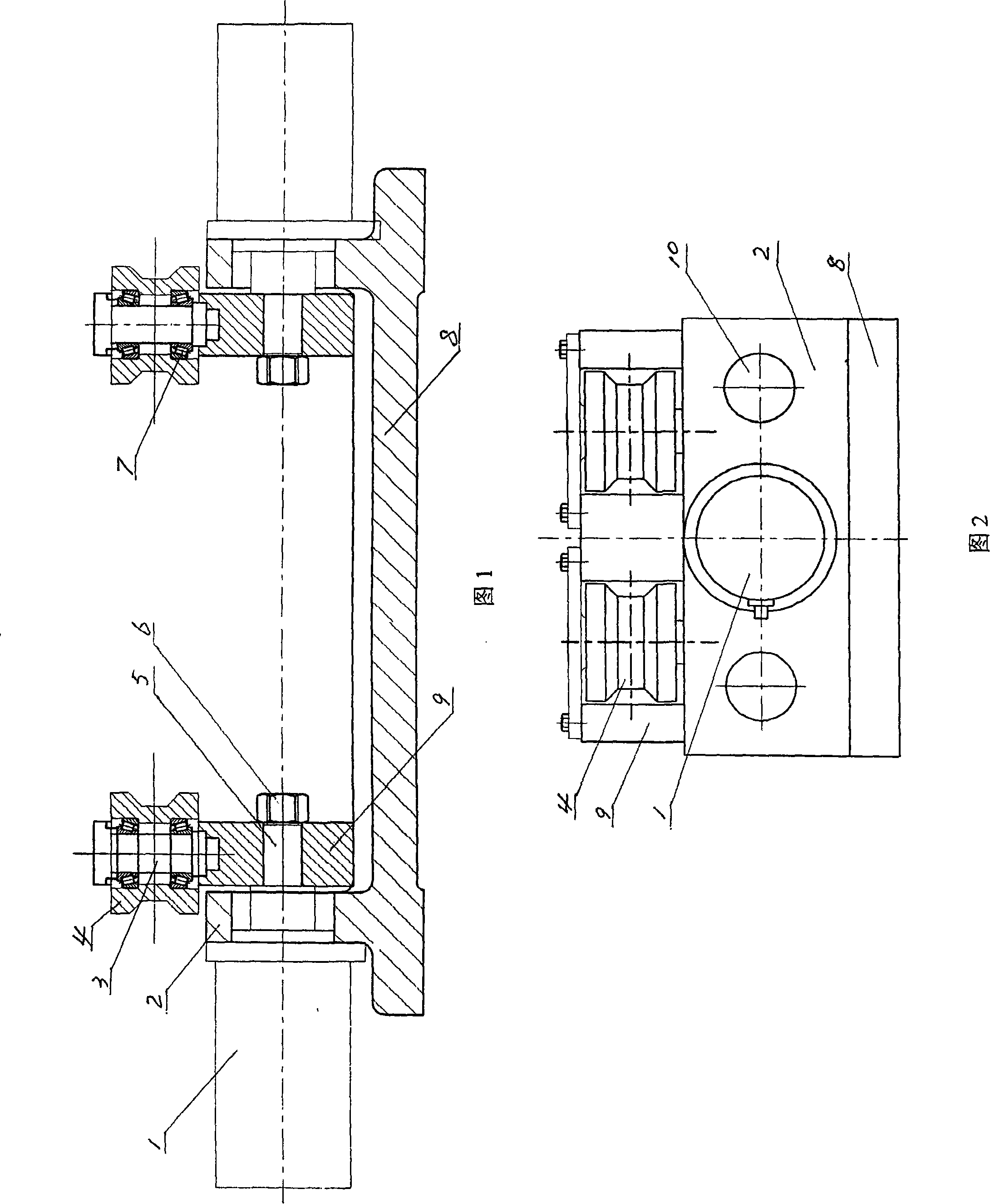
[0012] As shown in Figs. 1 and 2, the hydraulic centering device of the present invention includes a base 8 which is in the shape of a flat plate and two bosses 2 are provided on it. The two bosses are in the shape of a flat plate, and they are arranged upright and oppositely arranged. Their lower sides are integrated with the base 8 and three shaft holes are machined on their lower parts, and the three shaft holes are on the same level. The outer sides of the two bosses 2 are both fixed with an oil cylinder 1, the two oil cylinders are on the same axis, and the ends of their piston rods 5 respectively pass through the middle shaft hole at the lower part of the corresponding boss 2 and then extend into the inner side of the boss 2. A moving plate 9 is provided on the inner side of the two bosses 2, and three shaft holes are machined on the lower part of the moving plate 9, and the three shaft holes correspond to the three shaft holes on both sides of the lower part of the boss. Th...


PUM


Abstract

The invention discloses a hydraulic centering device, in particular a hydraulic centering device for preventing strip material from moving along the horizontal direction in the strip material rolling process. The hydraulic centering device is characterized in that the device comprises a pedestal and two bosses on the pedestal. The two bosses are arranged oppositely, and oil cylinders are arranged on the outer side of the bosses. The oil cylinders are arranged on the same axial line, and the piston rods of the oil cylinders respectively protrude inside corresponding bosses at the end section. Movable plates are arranged on the inner side of the two bosses, shaft holes are arranged on the lower section of the movable plates, and the piston rods are fixedly connected with the movable plates through nuts and the shaft holes. Both the movable plates have vertical shafts, and the two vertical shafts have guide wheels. The hydraulic centering device can improve the rolling quality and the rolling efficiency of the strip material.

Description

Technical field [0001] The invention relates to supporting equipment for a rolling mill. Specifically, it is a hydraulic centering device that prevents the strip from moving left and right in the horizontal direction during strip rolling. Background technique [0002] In the rolling mill production and application industries, it is known that in order to ensure the rolling quality of the strip, the longitudinal centerline of the strip must always be at the center of the two work rolls during the rolling process. In order to ensure that the longitudinal centerline of the strip is always at the center of the two work rolls, the traditional method is to install iron plugs on the stands at both ends of the work rolls of the rolling mill. Although the centering of the rolled strip can be realized by installing iron plugs on the stands at both ends of the work rolls of the rolling mill, since the iron plugs are fixed, the two sides of the rolled strip are easy to be roughened. Once the...

Claims


Application Information

Patent Timeline
IPC IPC(8): B21B39/14
Inventor 孙大南
Owner 朱惠兴
Why Eureka
Try Eureka