Sanitary napkin clad diverter and orientation diversion method

A technology for diverters and sanitary napkins, which is applied to cardboard items, etc., can solve the problems of insufficient air suction, poor applicability, and high manufacturing cost, and achieve the effects of solving insufficient negative pressure air suction, novel structural design, and ensuring reliable connection

Active Publication Date: 2008-08-27
HANGZHOU XINYUHONG INTELLIGENT EQUIP CO LTD
View PDF0 Cites 4 Cited by
  • Summary
  • Abstract
  • Description
  • Claims
  • Application Information

AI Technical Summary

Problems solved by technology

Its shortcomings: First, the negative pressure suction device adopts a continuous operation mode without discontinuities, which may easily cause the lack of connection between the previous process and the next process, affecting the normal work of the next process; Cause the sanitary napkin to fall from the negative pressure suction surface during operation; third, the structure is complex, the manufacturing cost is high, and the applicability is poor

Method used


Image

  • Sanitary napkin clad diverter and orientation diversion method

Examples


Embodiment 1

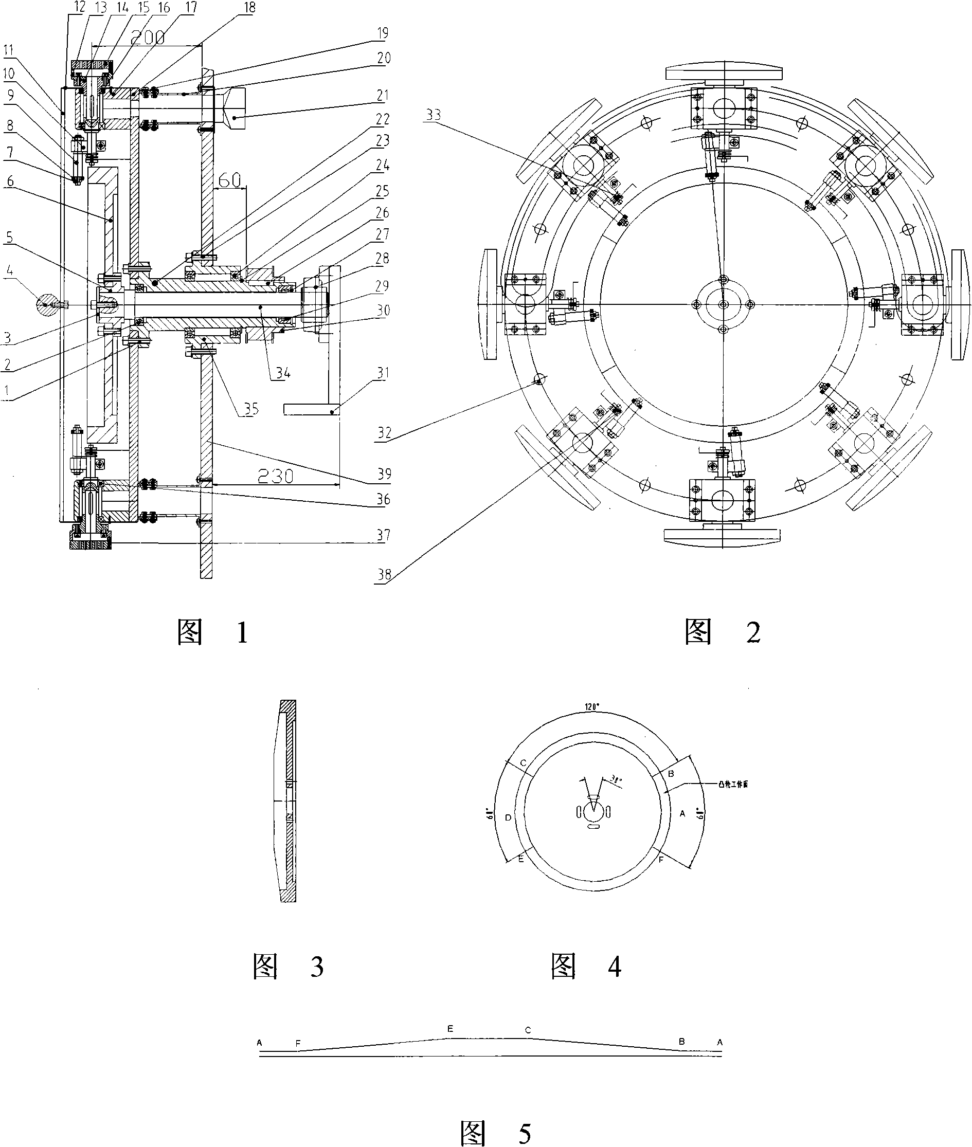
[0013] Embodiment 1: with reference to accompanying drawing 1~3. The sanitary napkin covers the diverter, the outer shaft 23 is processed by the prior art and is sleeved on the inner shaft 35 through the bearing 2, the bearing 30 and the retaining ring 28 for the hole, the inner shaft 35 is located on the bearing seat 29 of the support plate 32 and the inner Axle 35 does not rotate, and fixed disc 19 is enclosed within on the outer shaft 23 and adopts screw to be connected with outer shaft, and the cam working surface of end face cam 6 is the circumferential working surface that is formed by upslope, horizontal plane, downslope, and horizontal plane, and upslope is 120 degrees, 120 degrees for the downslope, and 60 degrees for the horizontal plane. The end face cam 6 is set on the inner shaft 35 through the flange plate 5 and is located on the side of the fixed plate 19. The baffle plate 3 is fixed on the end face of the inner shaft 35. Two or A plurality of negative pressure ...

Embodiment 2

[0014] Embodiment 2: On the basis of Embodiment 1, the azimuth transformation method of the sanitary napkin covering the steering gear, the power mechanism drives the outer shaft to rotate, the outer shaft drives the fixed disk to rotate, and the fixed disk drives the end of the pendulum shaft in the negative pressure suction device During the rotation of the bearing along the working surface of the end cam, the pendulum shaft drives the negative pressure suction device to rotate gradually through the connecting rod. (1) When the bearing moves to the highest end of the upward slope of the cam, the negative pressure suction device rotates 90 degrees , and then enter the horizontal plane of the cam working surface, and the negative pressure suction device does not rotate. (2) When the bearing shaft rotates from the cam level to the lowest surface of the cam downslope, when the bearing rotates to the cam’s upslope, the pendulum shaft passes through The connecting rod drives the ne...


PUM


Abstract

The invention relates to a novel sanitary towel coatding steering gear and a direction transferring method. An outer shaft is driven to rotate through a power mechanism; a fixed disk is driven to rotate through the outer shaft; during the process of a bearing at the end part of a negative pressure suction device being driven through the fixed disk to be rotated along an end surface cam working surface, a pendulum shaft drives the negative pressure suction device to rotate gradually through a connecting rod, (1) when the bearing moves to the maximum end on the upper sloping surface of the cam, the negative pressure suction device is rotated for 90 degrees and then gets to the horizontal plane of the working surface of the cam without being rotated, (2) when the bearing rotates from the horizontal plane of the cam to the minimum surface of the lower sloping surface of the cam, during the process that the bearing rotates to the upper sloping surface of the cam, the pendulum shaft drives the negative pressure suction device to rotate gradually through a connecting rod, and when the bearing moves to the minimum end of the lower sloping surface of the cam, the negative pressure suction device is reset and then gets into the horizontal plane of the working surface of the cam without being rotated, (3) when the bearing moves to the maximum end on the upper sloping surface of the cam, the negative pressure suction device is rotated for 90 degrees, in such a manner, the interstitial circulation is performed till the work is finished.

Description

technical field [0001] The invention relates to a novel sanitary napkin wrapping diverter and an azimuth conversion method, belonging to the field of sanitary napkin production equipment manufacturing. Background technique [0002] The structure design of the existing sanitary napkin wrapping steering gear: 1. The small bevel gears on the multiple negative pressure suction devices cooperate with the large bevel gears to achieve the purpose of azimuth conversion, and its working mode is continuous operation . 2. The suction port in the negative pressure suction device is the shaft suction port. Its shortcomings: First, the negative pressure suction device adopts a continuous operation mode without discontinuities, which may easily cause the connection between the previous process and the next process to be incomplete, affecting the normal operation of the next process; Cause the sanitary napkin to drop from the negative pressure suction surface during operation; the third i...

Claims


Application Information

Patent Timeline
Patent Type & Authority Applications(China)
IPC IPC(8): B31D1/04
Inventor 项逊华季儒茂
Owner HANGZHOU XINYUHONG INTELLIGENT EQUIP CO LTD
Why Eureka
Try Eureka