Inflatable pneumatic tyre

A technology of pneumatic tires and tires, which is applied to tire parts, tire sidewalls, transportation and packaging, etc., and can solve the problems of reducing appearance and difficulties

Inactive Publication Date: 2008-08-27
TOYO TIRE & RUBBER CO LTD
View PDF4 Cites 36 Cited by
  • Summary
  • Abstract
  • Description
  • Claims
  • Application Information

AI Technical Summary

Problems solved by technology

[0006] However, the method of limiting the surface roughness of the above-mentioned tire is a technique of spraying abrasive materials such as metal or glass hollow particles on the forming surface of the metal mold of the tire to adjust the forming surface to a specific roughness, which is suitable for adjusting the side surface of the tire. The roughness of a large area, but it is difficult to form a

Method used


Image

  • Inflatable pneumatic tyre
  • Inflatable pneumatic tyre
  • Inflatable pneumatic tyre

Examples


no. 1 approach

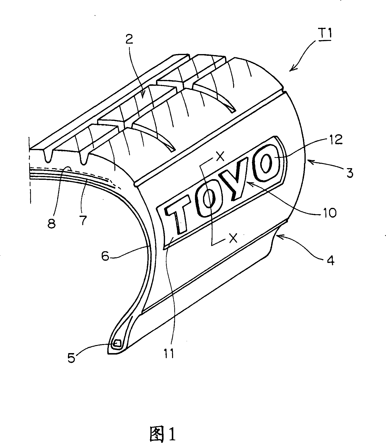
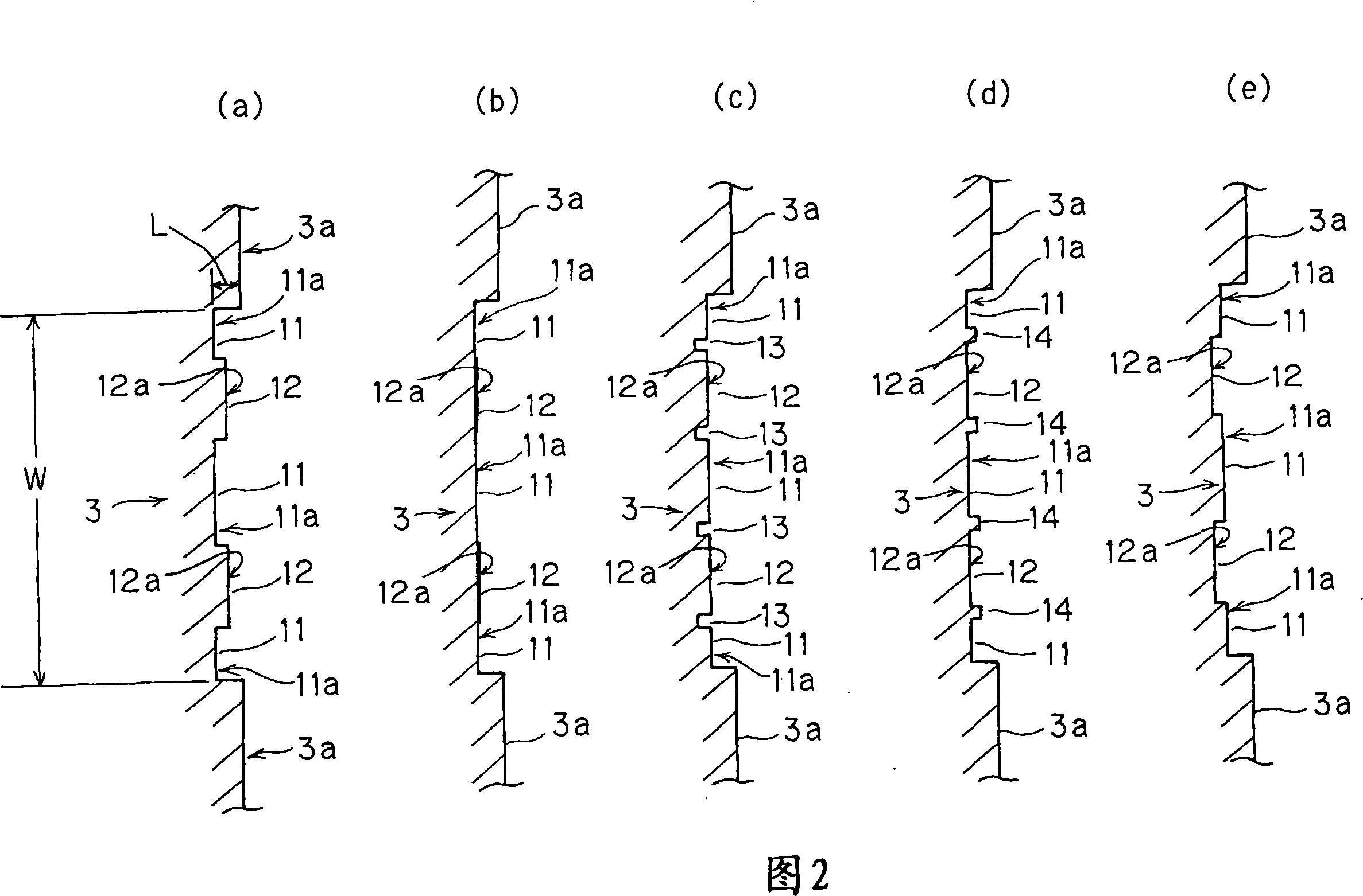
[0036] 1 is a perspective view of a half section of a tire, showing a sidewall surface of a pneumatic tire T1 (hereinafter, the pneumatic tire is simply referred to as a "tire") according to a first embodiment of the present invention, and Figs. 2(a) to (e) It is the X-X line sectional view in Fig. 1. In FIGS. 2( a ) to ( e ), for the sake of convenience, the curved surface of the side wall surface is developed into a plane and shown.

[0037] The tire T1 is composed of a tread portion 2, a sidewall portion 3, and a bead portion 4. The sidewall portion 3 extends outward in the radial direction of the tire from both ends of the tread portion 2; The outer end is connected and fixed to the rim flange. In this example, a radial tire for passenger cars is exemplified, which has a linear structure carcass 6 folded back around the tire bead core 5, a belt layer 7, and a belt reinforcement layer 8. The folded end of the carcass is locked; the belt layer 7 is arranged on the outer pe...

no. 2 approach

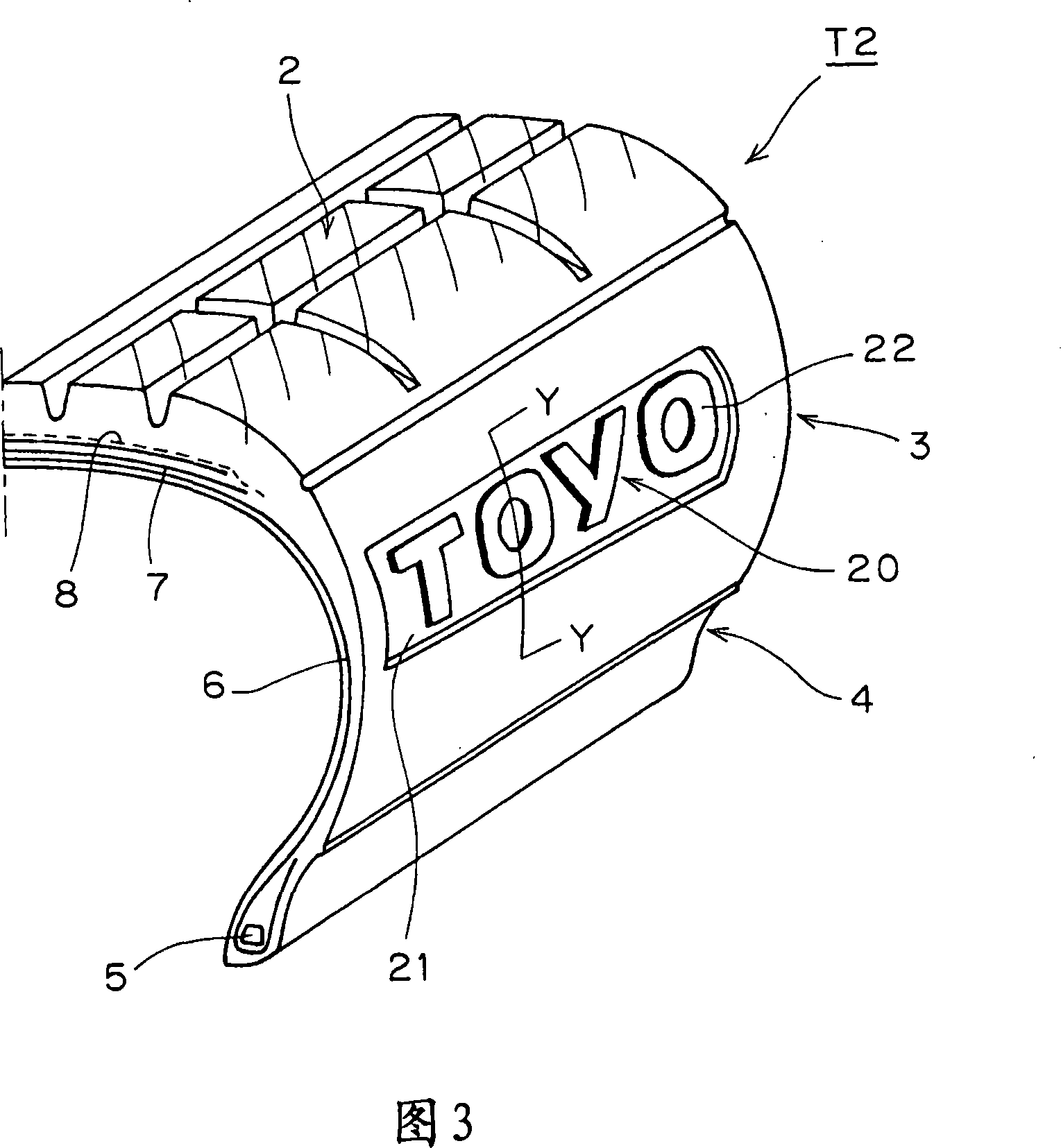
[0062] Fig. 3 is a perspective view of a tire half section, showing a sidewall surface of a tire T2 according to a second embodiment of the present invention. 4( a ) to ( e ) are cross-sectional views along line Y-Y in FIG. 3 . In FIGS. 4( a ) to ( e ), for the sake of convenience, the curved surface of the side wall surface is developed into a plane and shown.

[0063] The tire T2 is a radial tire for passenger vehicles having the same internal structure as the above-mentioned tire T1 (the same parts and components as the tire T1 are assigned the same symbols), and the name of the manufacturer is indicated on the surface of the side wall 3 of the tire T2. , brand name, tire size, etc. characters, numbers, symbols, or marks 22 used to indicate the rotation direction of the tire, design graphics used to decorate the side, etc. In FIG. 3 , the mark 22 is displayed as a character string (TOYO) as engraved characters.

[0064] Around the mark 22 is provided a background portion ...

no. 3 approach

[0084] Fig. 5 is a perspective view of a tire half section, showing the sidewall surface of a pneumatic tire T3 according to a third embodiment of the present invention, Fig. 6 is a partial sectional view along line X-X in Fig. Partial sectional view of Y-Y line. In FIGS. 6 and 10 , for the sake of convenience, the curved surface of the side wall surface is developed into a plane for representation.

[0085] The tire T3 is composed of a tread portion 2, a sidewall portion 3, and a bead portion 4. The sidewall portion 3 extends outward in the radial direction of the tire from both ends of the tread portion 2; The outer end is connected and fixed to the rim flange. In this example, a radial tire for passenger cars is exemplified, which has a linear structure carcass 6 folded back around the tire bead core 5, a belt layer 7, and a belt reinforcement layer 8. The folded end of the carcass is locked; the belt layer 7 is arranged on the outer periphery of the tread portion 2 of th...


PUM

PropertyMeasurementUnit
Arithmetic mean surface roughnessaaaaaaaaaa
Depthaaaaaaaaaa

Abstract

The invention provides an air tire, the displayed mark on sidewall surface of the air tire is excellent in visual identification extent, the air tire can in a long term maintain the visual identification extent of tire. The air tire (1) provided with a mark (12) on the sidewall (3) comprises the mark (12), a mark area (10) of a background part (11) of the mark which is inwardly formed via a concave surface in a direction from the sidewall surface to the tire shaft, and a convex surface forming mark (12) which is provided in a manner of protrusion on the mark area (10) corresponding to the concave surface, the surface of the mark (12) comprises a mirror surface part including surface roughness that arithmetic mean surface roughness (Ra) is 0.4 to 1.5 mum, the background part (11) comprises a rough surface part whose surface roughness is over 1.5 mum.

Description

technical field [0001] The present invention relates to a pneumatic tire, and more specifically, to a pneumatic tire having excellent visibility (visibility) of symbols such as letters, numerals, symbols, or figures provided on the sidewall surface. Background technique [0002] Conventionally, on the sidewall surface of the tire, there are letters, numbers, symbols indicating the name of the manufacturer, brand name, tire size, etc., or design patterns used to indicate the direction of rotation of the tire or to decorate the side and other graphic marks. [0003] Typically, the markings are represented by protruding from the sidewall surface. In addition, a decorative body is formed by engraving a plurality of fine grooves called ridges on the sidewall surface of the tire, and marks such as letters are represented by the decorative body. For example, in Japanese Patent Application Laid-Open No. 11-20416, ridges are engraved only on the characters as marks, and the phenome...

Claims


Application Information

Patent Timeline
IPC IPC(8): B60C13/00B60C13/02
Inventor 佐藤芳树中津留隆
Owner TOYO TIRE & RUBBER CO LTD
Why Eureka
Try Eureka