Gas flow regulating valve

A gas flow and regulating valve technology, which is applied in the direction of valve lift, valve detail, safety valve, etc., can solve the problems of small movement stroke, wear and elastic decline of shrapnel, and achieve fast dynamic response, high adjustment precision and simple structure.

Active Publication Date: 2010-06-02
WUHAN TIANHONG INSTR
View PDF8 Cites 5 Cited by
  • Summary
  • Abstract
  • Description
  • Claims
  • Application Information

AI Technical Summary

Problems solved by technology

[0004] This kind of valve is easy to be corroded because the shrapnel is directly placed in the fluid, and, in order to achieve a certain degree of elasticity, the shrapnel is usually processed thinner, and continuous work for a long time will cause fatigue, resulting in a decrease in elasticity and affecting the working performance of the valve.
Due to the extremely small movement stroke of the shrapnel, it is only suitable for a small flow range adjustment
There are also some ways to use threaded screw rods. The realization method is that one end of the threaded screw rod is placed at the cut-off port, and the other end is connected with the stepping motor through a slide bar. When the motor rotates, it drives the threaded screw rod to rotate and controls its operation. The feed rate can control the size of the cut-off port to achieve flow regulation. In order to achieve high flow regulation accuracy, the thread must be processed very finely, and the pitch is usually a few tenths of a millimeter. The regulating valve of this method is limited by the pitch. When a wide range of dynamic adjustment is required, its response speed is slow. In addition, the extremely fine thread will make it wear out quickly during continuous dynamic adjustment, reducing the service life of the valve.

Method used


Image

  • Gas flow regulating valve
  • Gas flow regulating valve
  • Gas flow regulating valve

Examples


Embodiment Construction

[0021] The above and other technical features and advantages of the present invention will be described in more detail below in conjunction with the accompanying drawings.

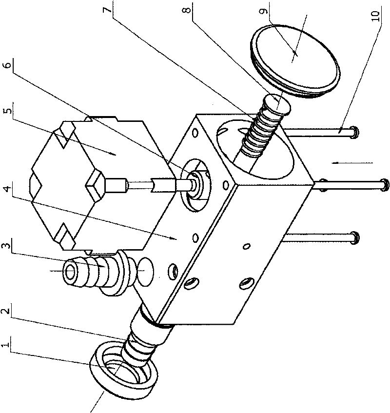
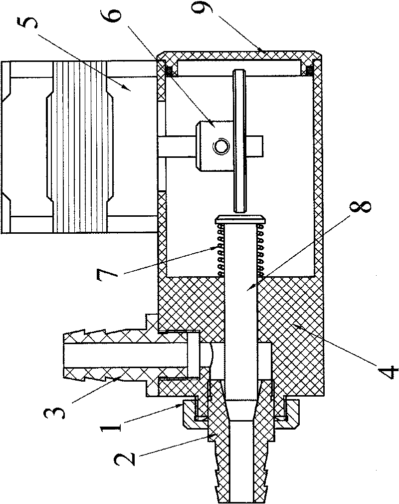
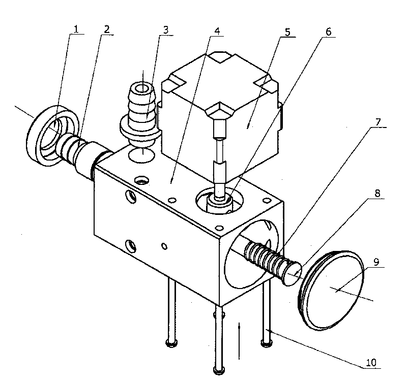
[0022] see figure 1 As shown, it is a three-dimensional exploded view of the gas flow regulating valve of the present invention; it includes a regulating valve main body 4, on which an air inlet nozzle 2 and an air outlet nozzle 3 are arranged. The valve main body 4 can be integrally formed (the present invention does not go into details on this, it is achievable for those skilled in the art by casting or welding), and it can also be independent from the regulating valve main body 4; a spool rod 8, which is arranged in the main body 4 of the regulating valve, and the main body 4 of the regulating valve is sealed by a gland 9; The tightness of the air inlet nozzle controls the effective diameter of the shut-off port, thereby controlling the amount of gas entering from the air inlet nozzle 2 and finally con...


PUM


Abstract

The invention relates to a gas flow regulating valve comprising a regulating valve body provided with an inlet nozzle and an outlet nozzle, wherein the inlet nozzle is provided with an inclination; avalve core bar is arranged in the regulating valve body, one end of the valve core bar is provided with a cone point fitting close to the inclination of the inlet nozzle; and a valve core bar actuating mechanism is used to control sealing degree between the valve core bar and the inlet nozzle, thereby controlling the gas inlet from the inlet nozzle.

Description

technical field [0001] The invention relates to a flow control valve, in particular to a gas flow regulating valve which can be continuously and rapidly adjusted dynamically. Background technique [0002] At present, there are many types of gas flow regulating valves at home and abroad, such as electromagnetic flow regulating valves. The realization method is that a stainless steel shrapnel is installed at one end of the valve core rod, and the shrapnel will naturally return to a flat state in an uncontrolled state. , when the other end of the spool rod is attracted by the electromagnetic force to overcome the tension of the shrapnel, the spool rod will produce a slight movement, and the movement stroke of the spool rod is controlled by the magnitude of the electromagnetic force, thereby controlling the size of the orifice to adjust the flow. [0003] Chinese patent ZL00201013.5 discloses a magnetic suspension suction type gas flow regulating valve port device. The valve por...

Claims


Application Information

Patent Timeline
Patent Type & Authority Patents(China)
IPC IPC(8): F16K17/36F16K1/38F16K31/04
Inventor 李虹杰李金平张培生杨颖汪天照范新峰
Owner WUHAN TIANHONG INSTR
Why Eureka
Try Eureka