
Data buffer apparatus and network storage system using the same and buffer method

A technology of network storage and cache storage, which is applied in the field of computer information, and can solve problems such as increasing the number of storage nodes, increasing the cost of storage systems, and crashing of storage nodes, that is, storage servers

Inactive Publication Date: 2008-08-27
INST OF COMPUTING TECH CHINESE ACAD OF SCI
View PDF0 Cites 28 Cited by
  • Summary
  • Abstract
  • Description
  • Claims
  • Application Information

AI Technical Summary

Problems solved by technology

[0005] The disadvantage of the existing network storage system that dynamically binds computing nodes and storage nodes is that when multiple computing nodes access the storage nodes at the same time, the processing speed of the computing nodes is much faster than the speed of accessing the storage nodes, and at a certain moment In the case of concurrent access, the speed bottleneck of accessing stored data will appear on the transmission medium or concentrated on the storage node
For example, when multiple computing nodes start, because the required data may be in the same storage node, this may cause a single computing node to start slowly and the user experience is not good; in severe cases, it may cause some computing nodes to blue screen or crash , and even cause the storage node, that is, the storage server to crash, causing the system to be paralyzed
[0006] One way to solve this problem is to add storage nodes to the entire network storage system. Although this method can solve this problem, it increases the number of storage nodes in the entire storage system at the same time, and accordingly greatly increases the cost of the storage system.

Method used


Image

  • Data buffer apparatus and network storage system using the same and buffer method
  • Data buffer apparatus and network storage system using the same and buffer method
  • Data buffer apparatus and network storage system using the same and buffer method

Examples


Embodiment Construction

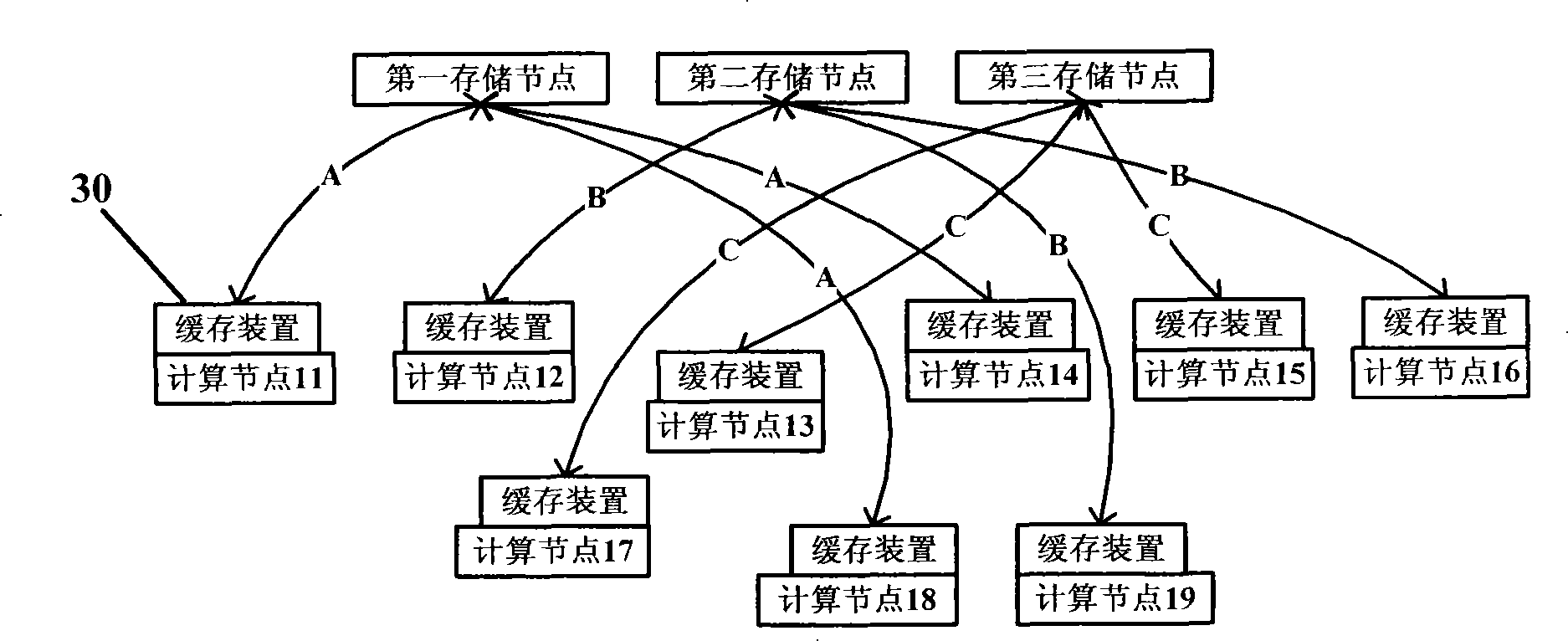
[0089] In order to make the purpose, technical solution and advantages of the present invention clearer, the data caching device, method and network storage system using the device of the present invention will be further described in detail below in conjunction with the accompanying drawings and embodiments. It should be understood that the specific embodiments described here are only used to explain the present invention, and are not intended to limit the present invention.

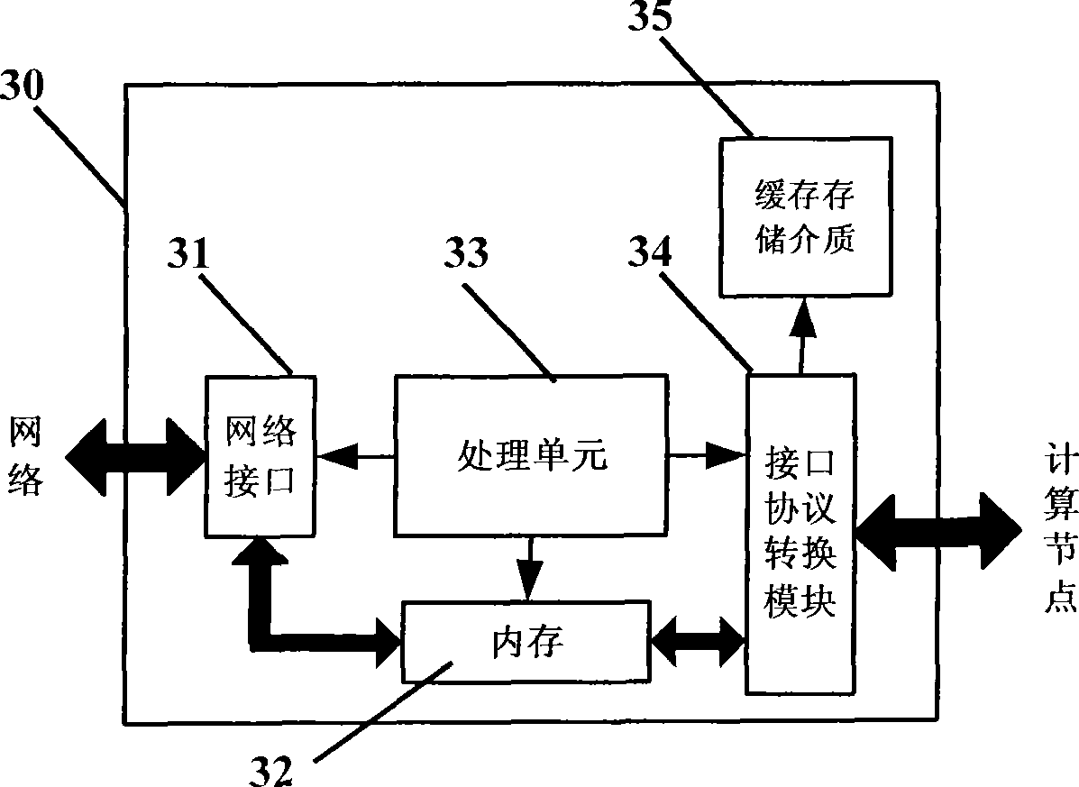
[0090] In order to achieve the purpose of the present invention, as figure 2 , 3As shown, as an implementable manner, the present invention provides a caching device 30, which is used in a network storage system that dynamically binds computing nodes and storage nodes, and is connected to the computing node and connected to the Storage nodes. The cache device 30 includes a network interface 31, a memory 32, a processing unit 33, a computing node interface protocol conversion module 34, and a cache st...


PUM


Abstract

The invention provides a data buffering device, the network memory system and the buffering method adopting the data buffering device. The buffering device includes a network interface; an EMS memory connected with the network interface and used for memorizing the data requested by computational nodes; a computational node interface protocol transformation module connected with the EMS memory, used for transforming the request of the computational nodes into the request of a peripheral equipment and then submitting the request to a processing unit and used for transmitting data together with buffering memory media; a processing unit connected with the computational node interface protocol transformation module, the network interface and the EMS memory and used for controlling the transmission of data and confirming the buffering relationship of data; buffering memory media connected with the computational node interface protocol transformation module and used for buffering data according to the buffering relationship confirmed by the processing unit. The invention can reduce the independence of the computational nodes on visiting memory nodes through the network, reduce network load and reduce the network load pressure of the whole system at a given time.

Description

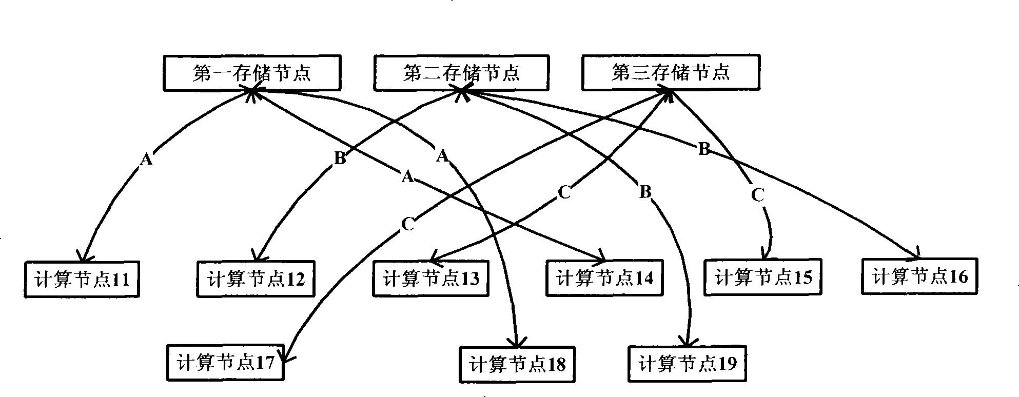
technical field [0001] The invention relates to the field of computer information technology, in particular to a data cache device under the environment of dynamically binding computing nodes and storage nodes, a network storage system and a cache method using the device. Background technique [0002] In an existing system that dynamically binds computing nodes and storage nodes, the data storage method adopts a centralized storage method. [0003] figure 1 Indicates the structure of a network storage system that dynamically binds computing nodes and storage nodes, including multiple storage nodes, that is, storage servers, and multiple computing nodes, which are connected through a network, and each computing node accesses the storage node through the network. [0004] figure 1 Only three storage servers and nine computing nodes are connected at a certain moment, and the transmission medium between them is the 100Mb network environment commonly used at present, as shown i...

Claims


Application Information

Patent Timeline
IPC IPC(8): H04L29/06H04L12/54H04L29/08
Inventor 孙清涛刘宇杨碧波韩晓明
Owner INST OF COMPUTING TECH CHINESE ACAD OF SCI
Learn More