Method for lubricating and cooling rollers and metal strips on rolling in particular on cold rolling of metal strips

A technology of metal strips and counter rolls, applied in the direction of rolls, metal rolling, metal rolling, etc., can solve problems such as high manufacturing costs

Inactive Publication Date: 2008-08-27
SMS DEMAG AG
View PDF2 Cites 20 Cited by
  • Summary
  • Abstract
  • Description
  • Claims
  • Application Information

AI Technical Summary

Problems solved by technology

If there is also environmental pressure due to clea

Method used


Image

  • Method for lubricating and cooling rollers and metal strips on rolling in particular on cold rolling of metal strips
  • Method for lubricating and cooling rollers and metal strips on rolling in particular on cold rolling of metal strips
  • Method for lubricating and cooling rollers and metal strips on rolling in particular on cold rolling of metal strips

Examples


Embodiment Construction

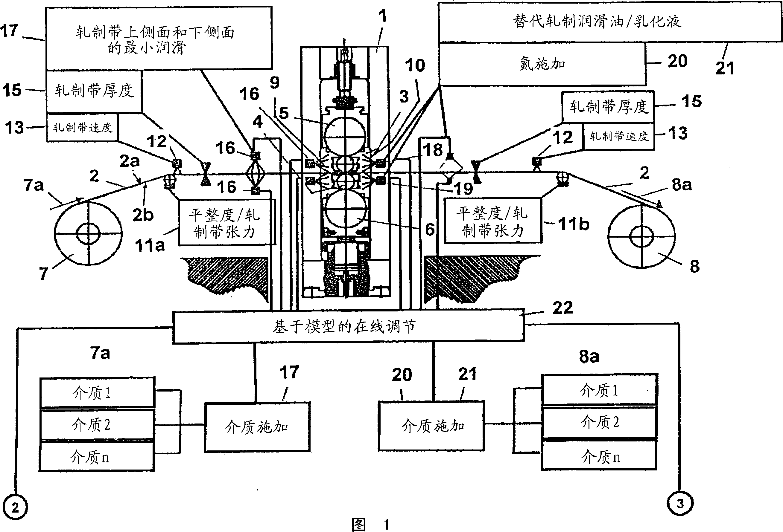
[0051] A rolling stand 1 ( FIG. 1 ) for a metal strip 2 (for example made of heavy or light metals of different alloys) has upper and lower work rolls 3 , 4 which are supported on backup rolls 5 in chocks , Between 6. Figure 1 shows a four-high rolling mill stand. The described application can be applied to all types of rolling stands, such as six-high rolling stands, twenty-high rolling stands, two-high rolling stands and the like. The metal strip 2 is guided from the uncoiling station 7 on the inlet side 7a to the winding station 8 on the outlet side 8a. On the inlet side 7a, a pure lubricant 9 is applied as a chemical component by spraying, and on the outlet side 8a, a coolant 10 is applied by spraying. The lubricant 9 and the coolant 10 consist of lubricating, scrubbing and inertizing materials or gases and also form combinations of these materials or gases and are fed to the lower side 2a of the rolling strip and to the rolling mill. Take it on side 2b. Emulsions with...


PUM


Abstract

The invention relates to a method for lubricating and cooling rollers (3,4,5,6) and metal strips (2) on rolling in particular, on cold rolling of metal strips (2), wherein, on the inlet side (7a) a minimal amount of pure lubricant (9) without a high water content is continuously supplied in an online controlled manner with a controlled viscosity and lubricity depending on a number of process data measurements (23) by means of a physical computer model (22) and the equivalent process data measurements (23) from the outlet side (8a) are also used online by the physical computer model (22).

Description

technical field [0001] The invention relates to a method for lubricating and cooling rolls and metal strips during rolling of metal strips, especially during cold rolling of metal strips, in which at least lubricant is applied on the inlet side and coolant is applied on the outlet side by spraying, And wherein the lubricating active, scrubbing and inerting material or gas (medium) or a combination thereof is fed to the lower side of the rolling belt and the upper side of the rolling belt and / or the lower working rolls or the upper work rolls. Background technique [0002] Such a method for cooling and lubricating rolls and rolling stock during cold rolling is known from EP 0 367 967 B1. Here, the oil / water emulsion containing the oil phase is adjusted according to the local tensile stress in the rolling strip or according to the gripping conditions between the roll and the rolling strip using a special emulsification technique , and it is calibrated by the use by amount an...

Claims


Application Information

Patent Timeline
IPC IPC(8): B21B37/32B21B37/44
CPCB21B3/00B21B27/10B21B37/26B21B37/32B21B37/44B21B45/0209B21B45/0218B21B45/0251B21B45/02
Inventor H·帕维尔斯基L·韦因加滕F·吉塞勒P·乔勒特H·-P·里克特
Owner SMS DEMAG AG
Why Eureka
Try Eureka