
Combine-harvester

A technology of combine harvester and harvesting section, applied in the direction of harvesters, cutters, agricultural machinery and implements, etc., can solve the problems of narrow space volume, grain damage, damage, etc., to reduce damage or blockage, damage or blockage change. less, and the effect of improving durability

Active Publication Date: 2008-09-03
ISEKI & CO LTD
View PDF1 Cites 22 Cited by
  • Summary
  • Abstract
  • Description
  • Claims
  • Application Information

AI Technical Summary

Problems solved by technology

[0003] In the technology described in the above-mentioned Patent Document 1, the conveying direction of the grains discharged by the discharge device is changed from the horizontal direction to the vertical direction (upper direction) in the connecting member, and it is formed so that it is delivered to the lower part of the vertical grain raising device for discharge while being pushed upwards. In addition, the vertical grain lifting device for discharging is used to lift the grain, so there is a problem that the grain is pushed from the rear when the grain is transported from the horizontal cylinder to the vertical cylinder, and the pressure of pushing up is applied to damage the problem.
[0004] In addition, since the transmission box part for accommodating the bevel gear is provided in the connection member, the space volume of the conveyance path of the grain in the connection member is narrowed, which not only causes damage to the grain, but also has the problem that clogging is likely to occur.

Method used


Image

  • Combine-harvester
  • Combine-harvester
  • Combine-harvester

Examples


Embodiment Construction

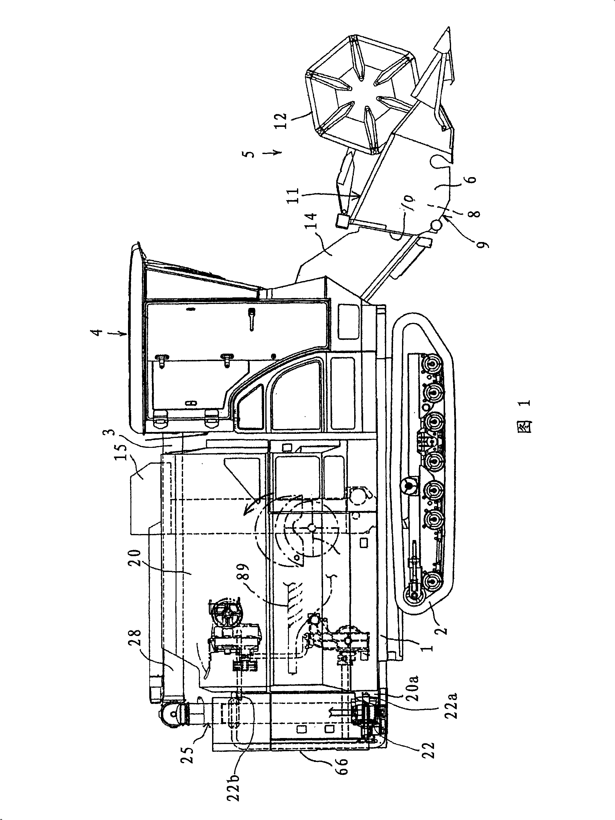
[0032] Embodiment of the combine of this invention is demonstrated using the example of the combine of the whole stalk insertion type.

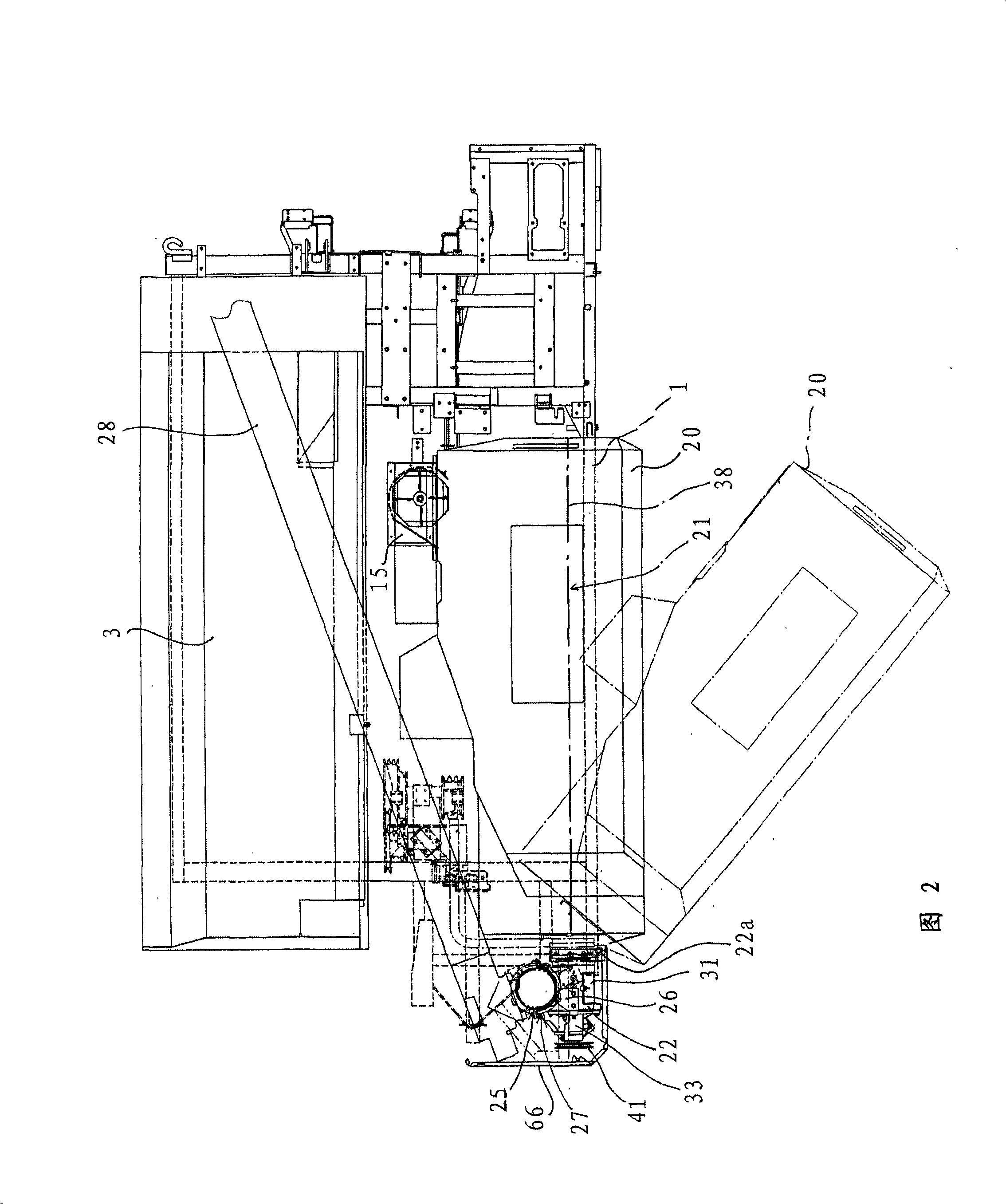
[0033] As shown in Fig. 1 and Fig. 2, a crawler-type walking device 2 is arranged on the lower side of the body frame 1, and a threshing device 3 is arranged on the upper side of the body frame 1. The harvesting section 5 is set up and down freely in front of the 4.

[0034] The structure of the harvesting part 5 mentioned above is demonstrated below.

[0035] First, use the left and right side walls 6 , the auger 8 that conveys the harvested grain stalks to the left and right sides, the bottom plate 9 located below the auger 8 , and the rear plate provided to connect the left and right side walls 6 and the bottom plate 9 . 10, constitute the push screw frame 11. Cylinder 12, cutter 13, push screw 8 are installed on this push screw frame 11.

[0036] And the front-end part of the conveyance elevator 14 is attached to the back side of this ...


PUM


Abstract

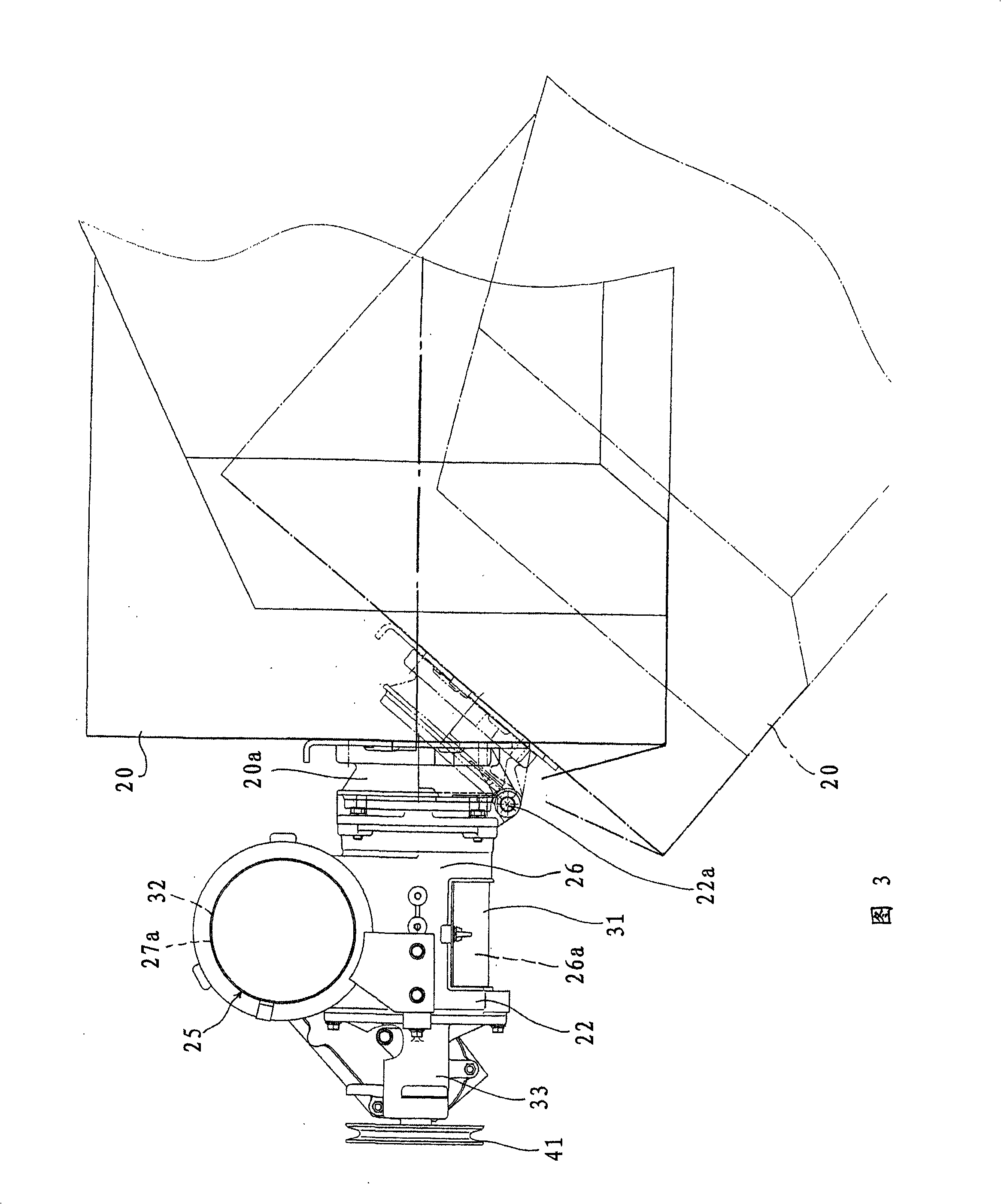
The invention ensures the width of grain transfer passage from a horizontal barrel to a vertical barrel in a connecting part, and reduces the damage and clog of transferred grains. The combine harvester comprises: a connecting part (22) having a horizontal barrel (26); a winnow device (25) connected on the upper part of the vertical barrel (27) of the connection part; a communication port (30) communicating the vertical barrel (27) with the horizontal barrel (26); a support barrel (36) of which the base part is mounted on the back wall (26b) of the horizontal barrel and the front end part is cantilevered; an input shaft (40) whose shaft supports on the front end part of the support barrel (36); a connecting part (24) connecting the front end part of the input shaft (40) to the back end part of the bottom exhaust spiral (38) of a grain tank (20); and a transmission mechanism (A) for the linkage of two shafts (40, 46) between an input shaft part backer than the back wall (26b) and the lower part of the winnow spiral shaft (46) of the winnow device (25).

Description

technical field [0001] The present invention relates to a combine provided with a grain tank and a grain discharge device. Background technique [0002] Conventionally, a combine harvester is well known in which a threshing device is provided above a body frame on which a traveling device is installed, a grain trough is provided on the side of the threshing device, and a device for discharging the grain trough to the outside is provided at the bottom of the grain trough. The bottom discharge device of the grain, the terminal of the bottom discharge device is connected on the horizontal cylinder part of the connection part, the lower part of the vertical valley device for the discharge of the valley is connected to the vertical cylinder part of the connection part, and the vertical valley device for the discharge is connected The upper part of the Yang Valley device is connected to the base of the discharge auger, and the above-mentioned connecting member vertically erects th...

Claims


Application Information

Patent Timeline
Patent Type & Authority Applications(China)
IPC IPC(8): A01D41/00A01F12/46A01F12/56
CPCA01D41/02A01D41/06A01D41/12A01D41/1208
Inventor 大原一志田上和成
Owner ISEKI & CO LTD
Learn More