Lower ram micromotion full-hydraulic counterblow hammer

A fully hydraulic, counter-hammer technology, which is applied to the driving device of the hammer, the drop hammer, etc., can solve the problems of poor gas controllability of counter-hammer, difficulty in realizing automatic control of striking energy, and large stroke.

Inactive Publication Date: 2008-09-03
张长龙
View PDF0 Cites 6 Cited by
  • Summary
  • Abstract
  • Description
  • Claims
  • Application Information

AI Technical Summary

Problems solved by technology

[0002] The existing domestic hammers are all gas-driven counter hammers in terms of driving principle, that is, the expansion of gas is used to drive the upper hammer head to drive the lower hammer head to move towards each other through mechanical linkage to achieve counter impact. The performance is poor, and it is difficult to realize the automatic control of the striking energy; from the perspective of the linkage mode of the upper and lower hammer heads, it is all mechanical linkage, and the upper and lower hammer heads are equal in energy and constant speed. Due to the high frequency of hammering, the reliability of mechanical linkage is poor; From the perspective of the moving speed and moving stroke of the upper and lower hammers, it is a constant speed and equal stroke. Since the lower hammer moves faster and has a larger stroke, it is not easy to operate.

Method used


Image

  • Lower ram micromotion full-hydraulic counterblow hammer

Examples


Embodiment Construction

[0013] Below in conjunction with the accompanying drawings, the micro-motion full-hydraulic counter hammer of the lower hammer head of the present invention will be further described.

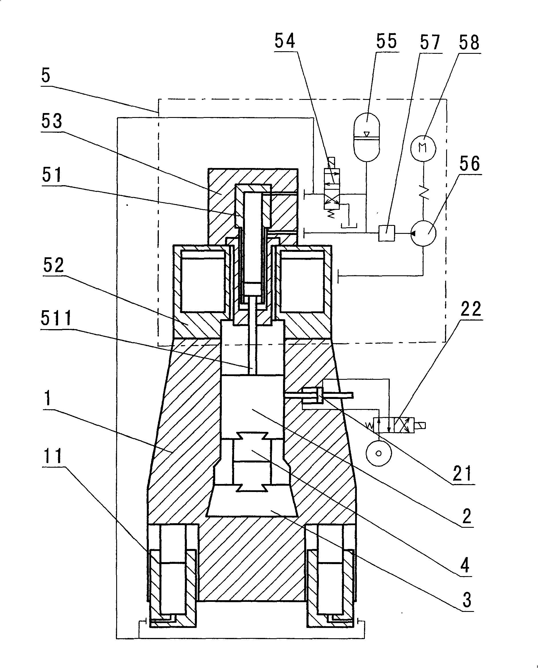
[0014] Such as figure 1 As shown, a lower hammer micro-motion full-hydraulic counter hammer includes a lower hammer 1, an upper hammer 2, a mold base 3, a mold 4, and a program-controlled full-hydraulic power head 5. The difference is that the above-mentioned lower hammer 1 There are balance hydraulic cylinders 11 on both sides of the bottom to realize the micro movement of the lower hammer 1, and the program-controlled full hydraulic power head 5 drives the movement of the upper hammer 2; the above-mentioned lower hammer 1 is a U-shaped whole, and the upper hammer 2 is on the lower hammer. 1 guide; the quality of the above-mentioned lower hammer head 1 is much greater than that of the upper hammer head 2.

[0015] The program-controlled full hydraulic power head 5 includes a working cylinder ...


PUM


Abstract

The invention discloses a full hydraulic counterblow hammer with a micro-displacement lower hammer head, which comprises a lower hammer head, an upper hammer head, a die holder, a die and a program-controlled full hydraulic power head. The invention is characterized in that balancing hydraulic cylinders are arranged at two bottom sides of the lower hammer head to achieve the micro-displacement of the lower hammer head, and the program-controlled full hydraulic power head drives the upper hammer head to move. The upper and the lower hammer heads hit to each other in a way of non-uniform velocity and unequal travel based on full hydraulic drive and hydraulic linkage. Both the movement velocity and travel of the lower hammer head are smaller than those of the upper hammer head. The counterblow hammer has the advantages of micro-displacement of the lower hammer head, full hydraulic drive, automatic control of hydraulic linkage and high reliability.

Description

technical field [0001] The invention relates to metal forming machining equipment, in particular to a hammer in a forging equipment, which utilizes full hydraulic drive and hydraulic linkage to realize the micro-movement of the lower hammer head and full hydraulic counter-hammer. Background technique [0002] The existing domestic hammers are all gas-driven counter hammers in terms of driving principle, that is, the expansion of gas is used to drive the upper hammer head to drive the lower hammer head to move towards each other through mechanical linkage to achieve counter impact. The performance is poor, and it is difficult to realize the automatic control of the striking energy; from the perspective of the linkage mode of the upper and lower hammer heads, it is all mechanical linkage, and the upper and lower hammer heads are equal in energy and constant speed. Due to the high frequency of hammering, the reliability of mechanical linkage is poor; Seen from the moving speed ...

Claims


Application Information

Patent Timeline
Patent Type & Authority Applications(China)
IPC IPC(8): B21J7/40B21J7/06
Inventor 张长龙
Owner 张长龙
Why Eureka
Try Eureka