
Up-down rotary display stand for forging steel ingot

A technology of lifting, rotating, and steel ingots, which is used in manufacturing tools, forging/pressing/hammer devices, forging/pressing/hammering machines, etc. It can solve problems such as limiting the range of forging specifications of steel ingots, bending and deformation of cylinder piston rods, and damage to cylinder seals. , to achieve the effect of improving the forging range, overcoming the eccentric load and improving the work efficiency

Inactive Publication Date: 2008-09-03
TAIYUAN HEAVY IND
View PDF0 Cites 17 Cited by
  • Summary
  • Abstract
  • Description
  • Claims
  • Application Information

AI Technical Summary

Problems solved by technology

The steel ingot U-turn device in the prior art can lift and rotate, but because the lifting is a rigid connection, when the steel ingot is placed on the U-turn device, its center of gravity cannot be guaranteed to fall on the center of the device, so there is an eccentric load on the lifting cylinder. As a result, the seal of the oil cylinder will be damaged, and the piston rod of the oil cylinder will be bent and deformed, resulting in failure of the oil cylinder and affecting work efficiency
In addition, the steel ingot U-turn device in the prior art has a single V-shaped support frame for the steel ingot, which limits the specification range of the steel ingot forging

Method used


Image

  • Up-down rotary display stand for forging steel ingot
  • Up-down rotary display stand for forging steel ingot

Examples


Embodiment Construction

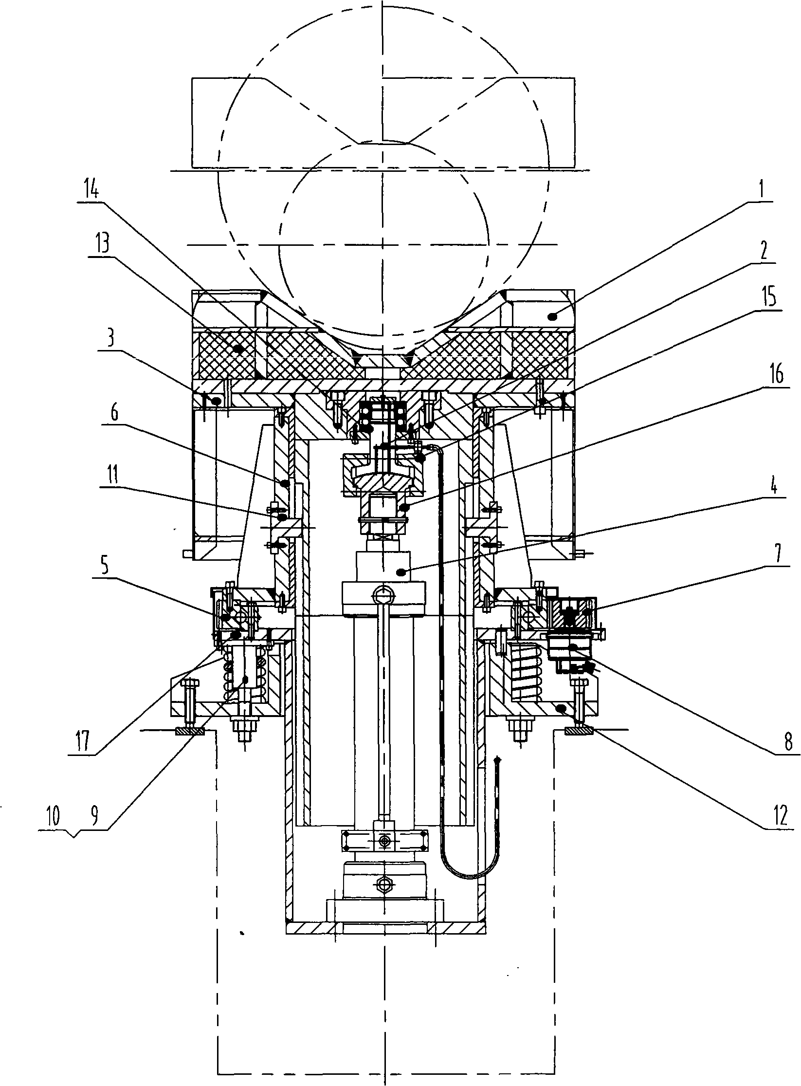
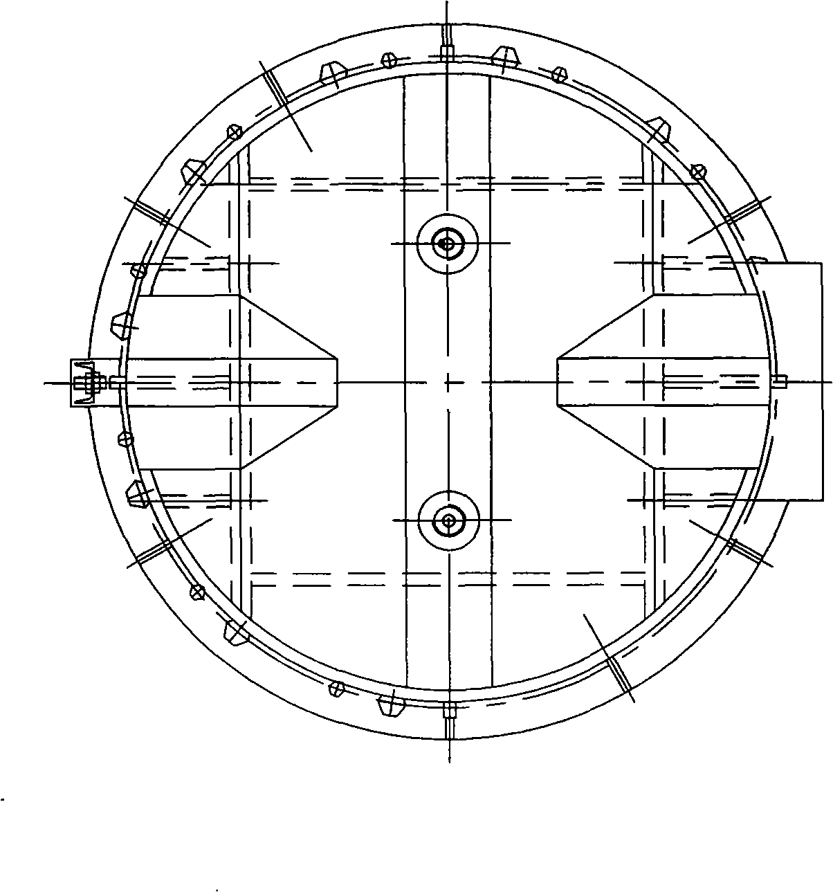
[0013] Such as figure 1 , 2 As shown, a lifting and rotating platform for forging steel ingots includes: a lifting device, a rotating device and a base. The clamping block 15, the spherical joint 16, and the lifting cylinder 4 are formed. The steel ingot supporting platform 1 is bolted to the rotary lifting platform 3 and supported on the upper end surface of the thrust bearing 14. The thrust bearing 14 is connected to the stop of the supporting block 2, and the supporting block 2 and the spherical joint 16 pass through the clamping block. 15 is connected, and the spherical connection head 16 is threadedly connected with the piston rod of the lifting cylinder 4, and the lifting action of the steel ingot lifting rotary table is realized when the piston rod of the lifting cylinder 4 rises or falls.

[0014] Described rotating device is made of the turntable bearing 5 with external tooth, rotating guiding bracket 6, pinion 7, variable motor 8, guide key 11. Four pieces of guid...


PUM


Abstract

A lift / rotation bench for forging steel ingots is provided, which belongs to the field of forging tools. The steel ingot-turning device in the prior art has the disadvantages such as offset load of the hoist cylinder during the placement of steel ingots and single V-shaped structure of the steel ingot supporter. In the invention, a reticulated V-shaped steel ingot supporter is connected with a frame of the lift / rotation bench and also supported against the top end surface of a thrust bearing; the thrust bearing is connected with a bearing block; the bearing block is connected with a spherical joint through a clamping block; the spherical joint is connected with a hoist cylinder; a rotary guide bracket is fixed thereon with a guide key; the guide key is in socket joint with a guide groove on the lift / rotation bench; the rotary guide bracket is fixed to the outer ring of a turntable bearing; the external teeth of the turntable bearing are engaged with a pinion gear; the pinion gear is driven by a variable motor, a supporter is fixed to the inner ring of the turntable bearing and positioned above a spring; and the supporter is arranged on a pedestal. The bench overcomes the problem of offset load of the hoist cylinder, avoids the failure of the oil cylinder, improves the work efficiency, and widens the range of forging specifications of steel ingots.

Description

technical field [0001] The invention relates to a forging tool, in particular to a tool for turning around a steel ingot blank during a forging operation. Background technique [0002] The steel ingot lifting and rotating table is a transitional device between the forging main machine and the manipulator. During forging, the crane hoists the steel ingot blank to be forged on the steel ingot lifting and rotating table, and then the steel ingot is clamped by the manipulator and sent to the main machine for forging. Due to technological requirements, the steel ingot blank often needs to be forged in a U-turn. The forged end is clamped by the manipulator and moved out of the main machine, and placed on the steel ingot lifting and rotating table. After being rotated, it is clamped by the manipulator into the main machine for forging. At present, most of the forging equipment in the entire forging industry in China was manufactured in the late 1950s and early 1960s, and the level...

Claims


Application Information

Patent Timeline
IPC IPC(8): B21J13/08
Inventor 邢建斌
Owner TAIYUAN HEAVY IND
Learn More