
Diesel engine piston cooling nozzle testing tool and use method thereof

A piston cooling nozzle and detection tooling technology, applied in the direction of mechanical measuring devices, testing of mechanical components, testing of machine/structural components, etc., can solve problems such as cylinder scuffing, cylinder scuffing failure, and insufficient pressure, and achieve a simple overall structure, Avoid the failure of the cylinder, and the effect of strong practicability

Inactive Publication Date: 2016-02-03
ANHUI QUANCHAI ENGINE
View PDF6 Cites 5 Cited by
  • Summary
  • Abstract
  • Description
  • Claims
  • Application Information

AI Technical Summary

Problems solved by technology

If the engine piston cannot be cooled and lubricated normally at high temperature, the material of the moving parts will expand as the temperature rises, which will gradually reduce the matching gap between the piston and the cylinder liner and form a protective oil film, which will cause metal dry friction and cause The fault that the car cannot be started after the hot car stops, and in severe cases, it may cause cylinder scuffing
Therefore, the correctness of the injection angle and fuel injection quantity of the piston cooling nozzle is extremely important. When the pressure of the piston cooling nozzle is insufficient, the injection is weak, and the injection angle is wrong, it will usually cause the engine to be difficult to start and the cylinder to fail.

Method used


Image

  • Diesel engine piston cooling nozzle testing tool and use method thereof
  • Diesel engine piston cooling nozzle testing tool and use method thereof
  • Diesel engine piston cooling nozzle testing tool and use method thereof

Examples


Embodiment Construction

[0023] The embodiments of the present invention are described in detail below. This embodiment is implemented on the premise of the technical solution of the present invention, and detailed implementation methods and specific operating procedures are provided, but the protection scope of the present invention is not limited to the following implementation example.

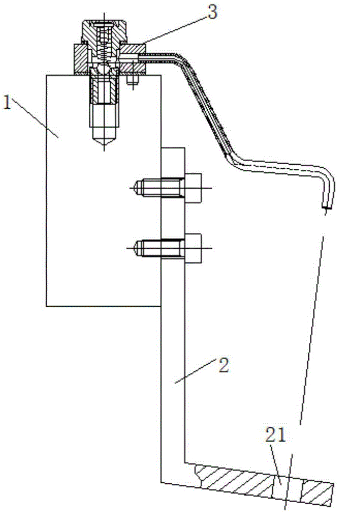
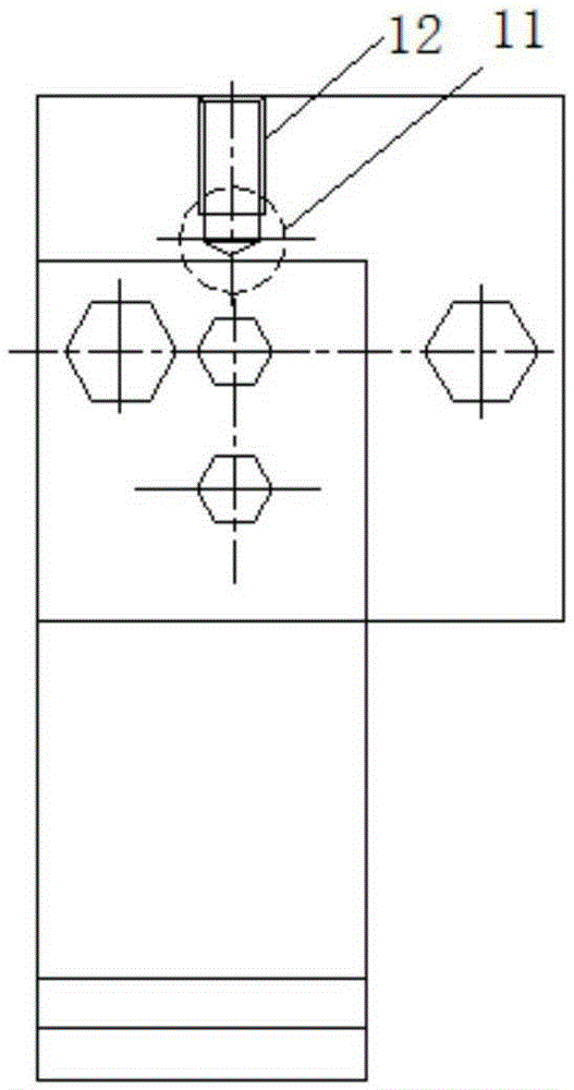
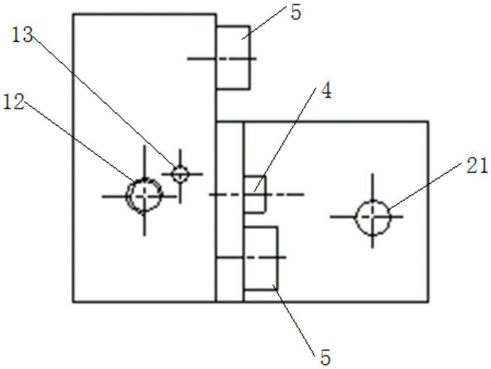
[0024] like Figure 1~3 As shown, the present embodiment includes a bottom plate 1 and a backing plate 2. The back side of the bottom plate 1 is provided with a φ16 oil inlet hole 11 for communicating with the nozzle 3 to be tested and an external oil inlet pipe. The nozzle 3 to be tested is arranged on the top of the bottom plate 1. The backing plate 2 includes an integrally formed vertical part and a horizontal part, one end of the vertical part is connected to the front of the bottom plate 1, the other end of the vertical part is connected to the horizontal part, and the gap between the horizontal part and the v...


PUM


Abstract

The invention discloses a diesel engine piston cooling nozzle testing tool and a use method thereof. The tool comprises a bottom plate and a backing plate. A diesel inlet port communicating a to-be-tested nozzle and an external diesel inlet pipe is arranged in the back surface of the bottom plate. The to-be-tested nozzle is arranged on the top of the bottom plate. The backing plate comprises a vertical part and a transverse part. One end of the vertical part is connected to the front face of the bottom plate, and the other end of the vertical part is connected with the transverse part. An inclined included angle between the transverse part and the vertical part is consistent with the angle of the to-be-tested nozzle. A testing through hole matching the to-be-tested nozzle is arranged on the transverse part. The bottom plate and the backing plate are assembled to form a combined part. The to-be-tested nozzle is installed on the top of the bottom plate. The diesel inlet port of the bottom plate is connected with the external diesel inlet pipe, and then the bottom plate and the backing plate are fixed on a testing bench. A measuring cylinder is placed right under the testing through hole. A diesel pump is turned on and timing is carried out. A diesel injection amount is obtained within a set time. The tool can accurately measure the position of the cooling nozzle relative to a piston and the diesel injection amount and has a simple overall structure.

Description

technical field [0001] The invention relates to a detection tool, in particular to a detection tool for a diesel engine piston cooling nozzle and a using method thereof. Background technique [0002] With the continuous strengthening of diesel engines, the heat load of pistons is getting higher and higher. In order to meet the requirements of diesel engines, pistons with integral internal cooling oil chambers, steel top aluminum skirts, integral forged steel, composite materials, and cast iron pistons have emerged as the times require. These The pistons of high-load diesel engines are generally designed with an internal cooling oil chamber. The cooling oil is sprayed into the cooling oil chamber through the nozzle, and flows out after oscillating in the oil chamber to absorb the heat of the piston, thereby reducing the temperature of the piston (especially the head). The cooling nozzle is generally a cooling device fixed on the engine body. When the piston reciprocates at hi...

Claims


Application Information

Patent Timeline
IPC IPC(8): G01B5/00G01M13/00
Inventor 蔡兴玲
Owner ANHUI QUANCHAI ENGINE
Learn More