Eureka AIR delivers breakthrough ideas for toughest innovation challenges, trusted by R&D personnel around the world.

Bottle blow-moulding machine die carrier/mold component

A blow molding machine and mold technology, which is applied to home appliances, other home appliances, applications, etc., can solve the problems of not being able to meet the needs of small-bottle beverages, and the speed cannot be increased, and achieve the effects of simple structure, improved production efficiency, and reduced volume

Active Publication Date: 2008-09-03
GUANGZHOU TECH LONG PACKAGING MACHINERY CO LTD
View PDF0 Cites 5 Cited by
  • Summary
  • Abstract
  • Description
  • Claims
  • Application Information

AI Technical Summary

Problems solved by technology

In this way, when blowing a small bottle type, since the speed cannot be increased too much (only a slightly higher speed can be set), it restricts the increase in the blowing output of a single machine, so it is far from meeting the needs of consumption. Market demand for small bottle beverages

Method used


Image

  • Bottle blow-moulding machine die carrier/mold component
  • Bottle blow-moulding machine die carrier/mold component

Examples


Embodiment Construction

[0018] The present invention will be further described below in conjunction with the accompanying drawings and specific embodiments.

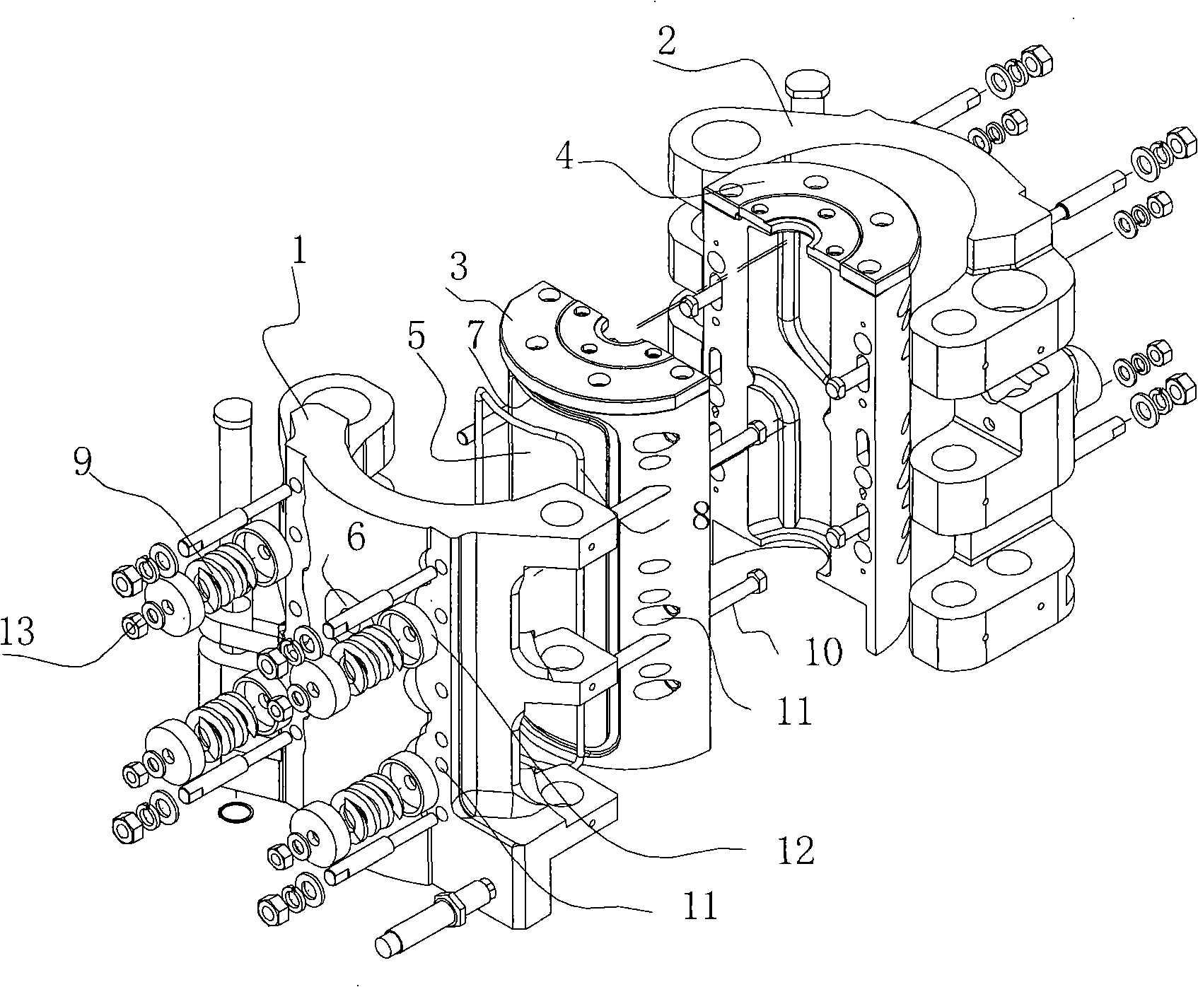
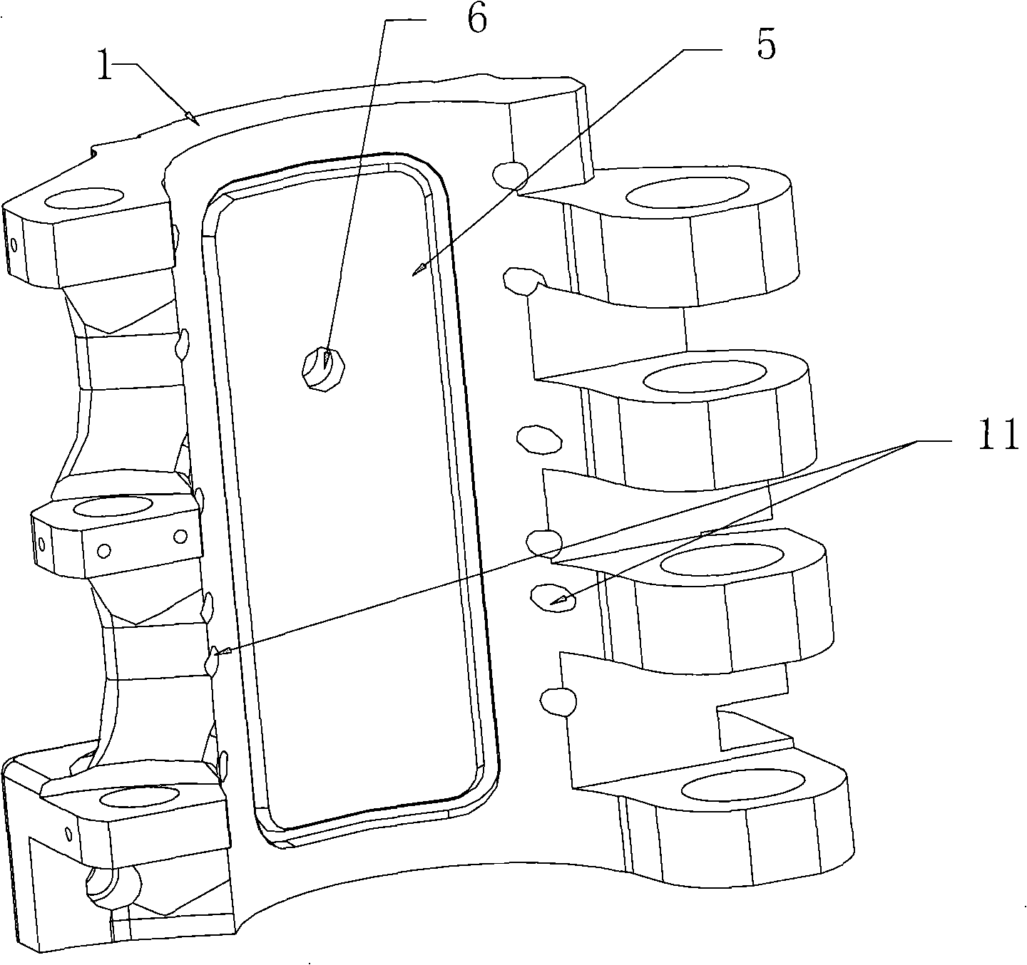
[0019] see figure 1 , figure 2 , the bottle blowing machine mold assembly of the present invention comprises left mold base 1, right mold base 2 and left mold 3, right mold 4, and described left and right molds 3,4 are installed in left and right mold bases 1,2, between mold and mold A sealing compensation device is provided between the frames, and the sealing compensation device includes an inner concave part 5 correspondingly provided on the outer wall of the mold or the inner wall of the mold frame. A sealing ring 8 is arranged around the inner concave part 5. The inner recess 5 forms a closed cavity, and an air hole 6 communicating with the closed cavity is also provided on the formwork. The inner recess 5 is along the left formwork (such as figure 2 ) or left mold (such as figure 1 ) for portrait settings.

[0020] exist figure 1 A...


PUM


Abstract

The invention discloses a mold frame / mold assembly of a bottle blowing machine, which comprises a left and a right mold frames and a left and a right molds, wherein the seal compensation device is arranged between a mold and a mold frame and includes recessed sections correspondingly arranged on the outer side wall of the mold and the inner sidewall of the mold frame, and a seal ring arranged on the periphery of the recessed section; the recessed sections can form a closed cavity when the mold frame snap-fits the mold; and an air hole communicating with the sealed cavity is arranged on the mold frame. The mold assembly of the bottle blowing machine obviates the need of moving mold sleeve and static mold sleeve, thus greatly reducing the size of the mold assembly. Accordingly, the number of mold cavities can be increased in single machine, thus improving the production efficiency of single machine. The mold frame / mold assembly is particularly suitable for full-automatic bottle blowing machine with a volume smaller than 600 ml and high requirement for single-machine yield. The mold frame / mold assembly has simpler structure.

Description

technical field [0001] The invention relates to beverage bottle processing equipment, in particular to a blow molding machine mold frame / mould assembly. Background technique [0002] At present, the demand for beverage bottles below 600ml in the market is increasing, accounting for about 70% of the market share, and there is still a growing trend. However, the output of a single bottle blowing machine cannot be increased due to the constraint of the number of cavities. Because, at present, the automatic bottle blowing machines at home and abroad can blow bottles of various specifications (from 300ml-2000ml) on the same machine, so a movable mold set and a fixed mold set are set between the mold and the mold base. , to adapt to the rapid replacement and installation of molds of various specifications, to meet the market demand for certain specifications of beverages, so the shape design of the mold base is relatively large, so the number of cavities on a single machine canno...

Claims


Application Information

Patent Timeline
Patent Type & Authority Applications(China)
IPC IPC(8): B29C49/08B29L22/00
CPCB29C2049/5633
Inventor 吴志刚邹高辉
Owner GUANGZHOU TECH LONG PACKAGING MACHINERY CO LTD
Why Eureka
Eureka Blog
Learn More