

Vehicle body structure
A car body and structure technology, applied in the direction of upper structure, vehicle parts, upper structure sub-assembly, etc., can solve problems such as excessive response delay, bumper deformation, etc., achieve simple structure, ensure cooling performance, and easy deformation effect
- Summary
- Abstract
- Description
- Claims
- Application Information
AI Technical Summary
Problems solved by technology
Method used
Image

Examples
Embodiment Construction
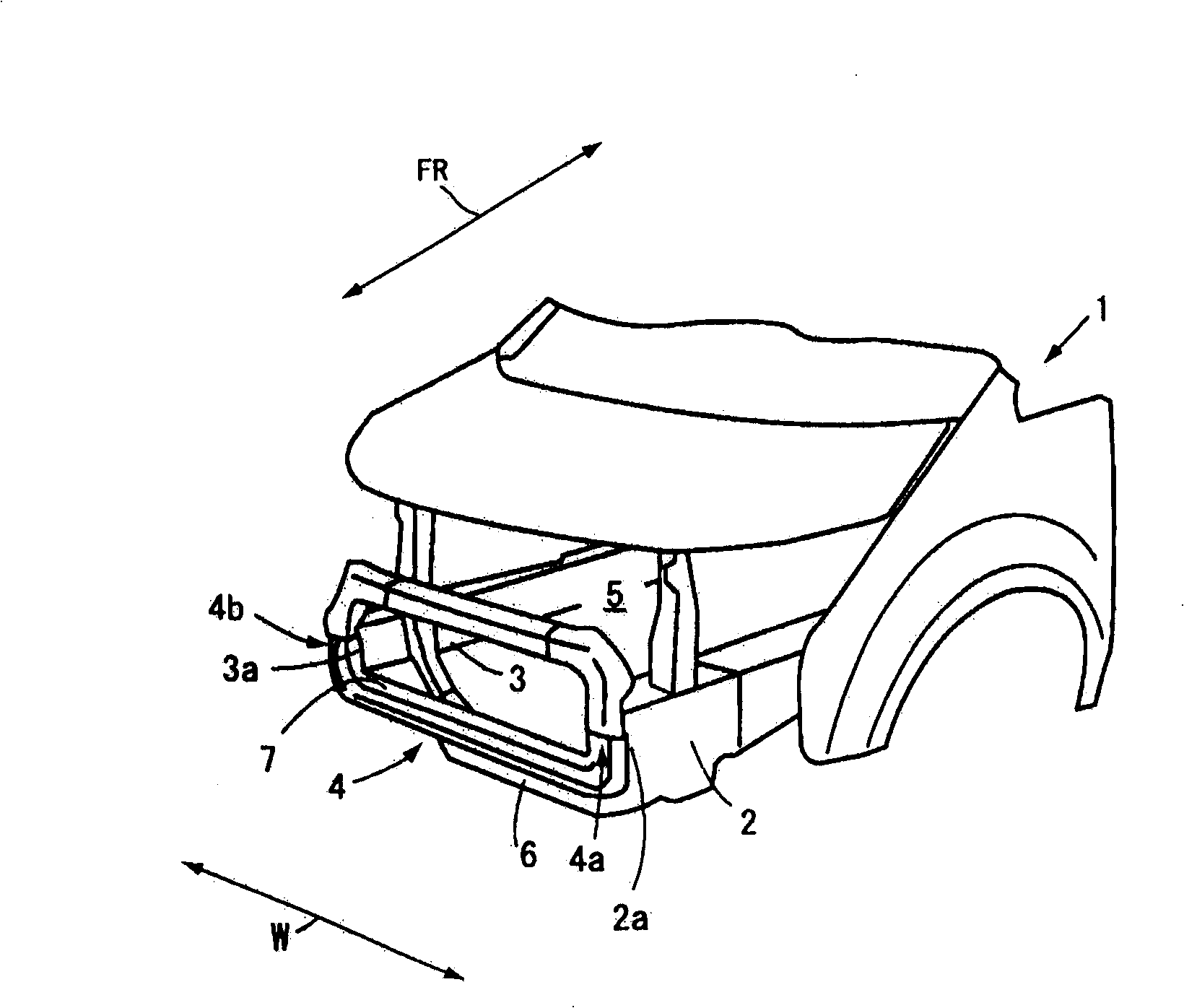
[0035] Next, use Figure 1 to Figure 5 A first embodiment of the present invention will be described. pass figure 1The vehicle indicated by the symbol 1 includes: a pair of front side members 2, 3 extending in the front-rear direction of the vehicle body indicated by the arrow FR and arranged in the vehicle width direction indicated by the arrow W; a bumper 4 , whose two ends 4a, 4b are connected to the front ends 2a, 3a of the front longitudinal beams 2, 3; The space indicated by the symbol 5 represents the engine compartment covered by the front side members 2 and 3 , the bumper 4 and the front cross member 6 .
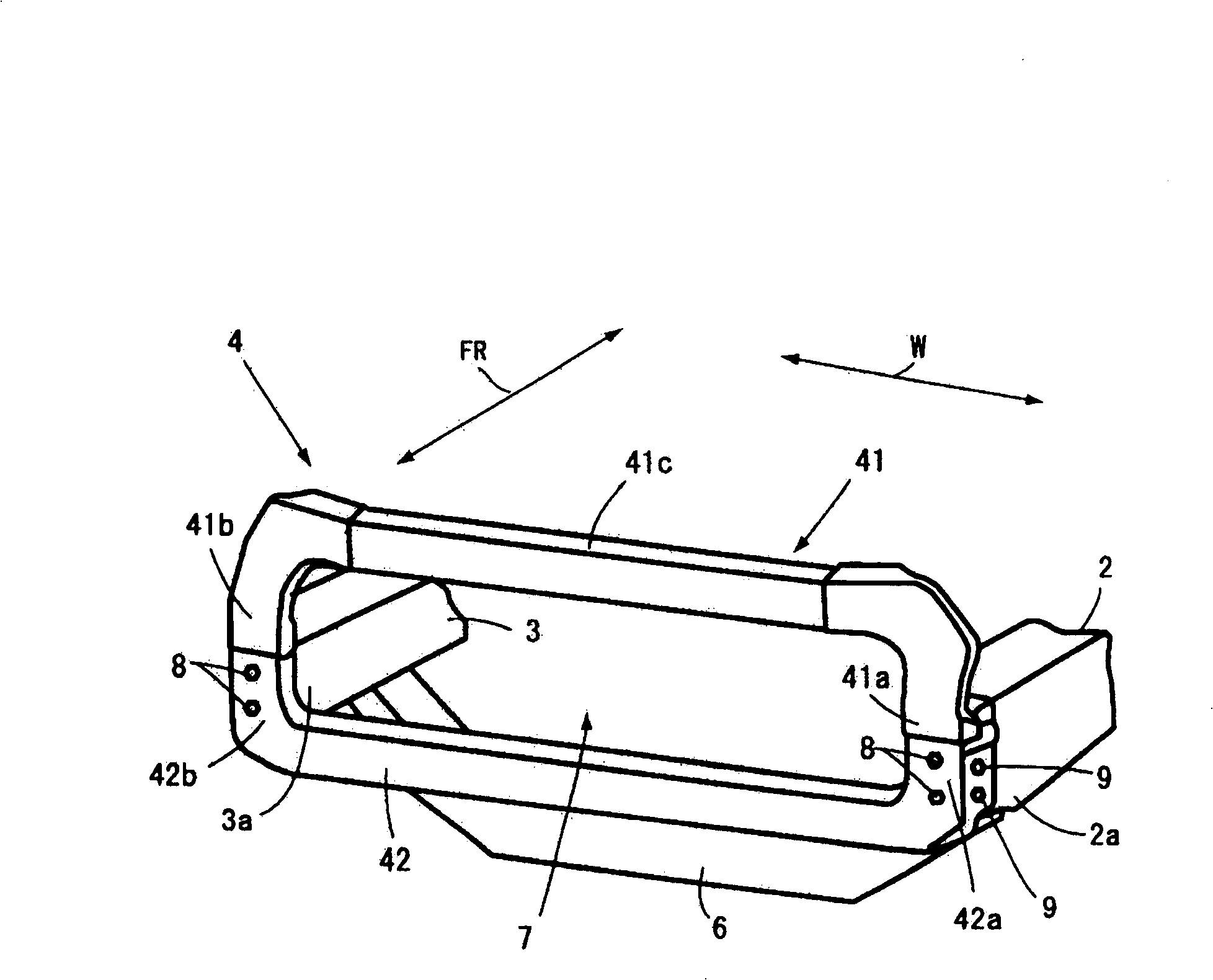
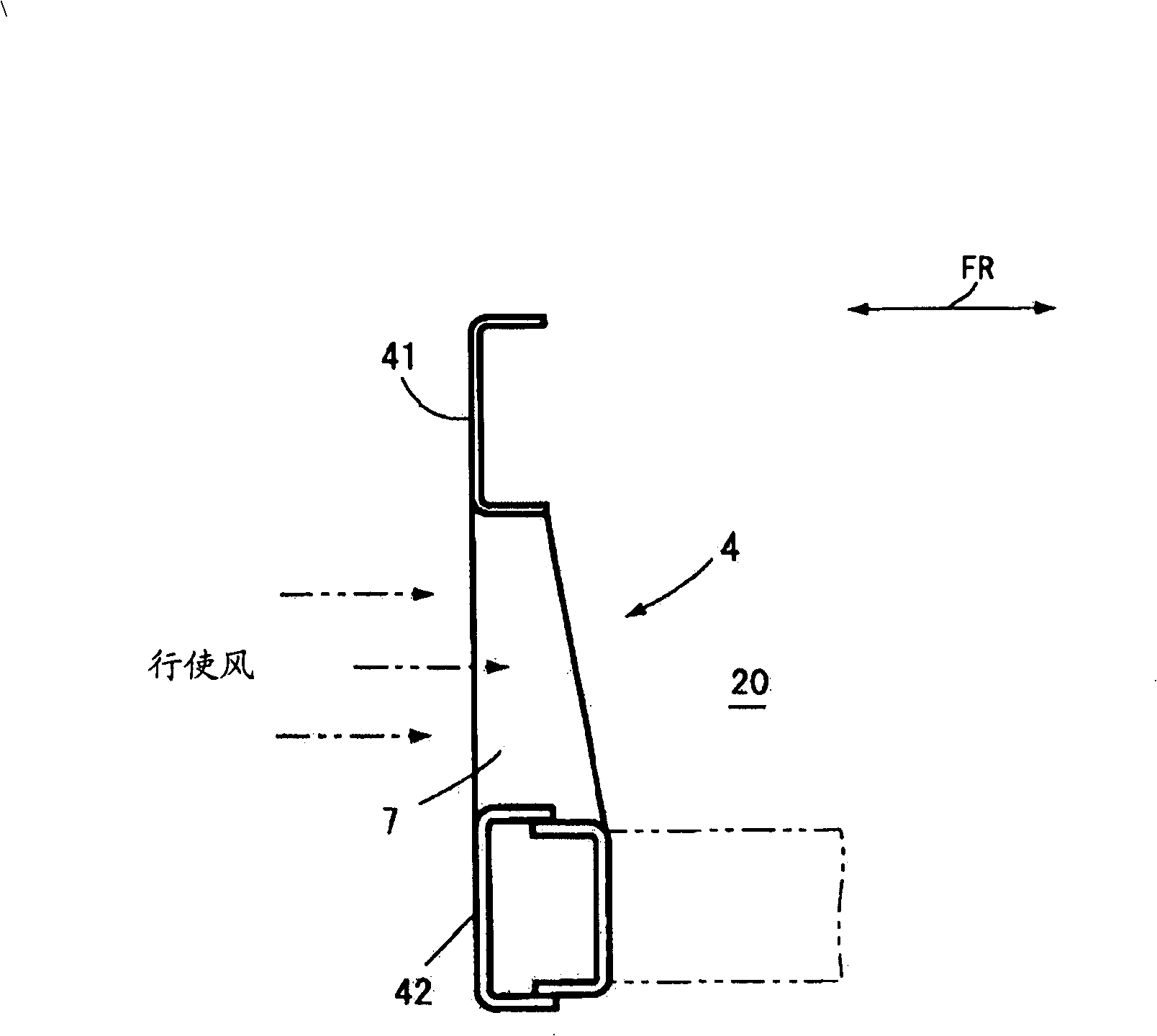
[0036] bumper 4 as figure 2 As shown, it includes: a lower member 42, whose two ends 42a, 42b are connected to the front ends 2a, 3a; and an upper member 41, which has a connecting beam 41c above the front ends 2a, 3a, and the two ends 41a, 41b are connected to On the front end 2a, 3a. The upper member 41 and the lower member 42 are press-formed products, and ...
PUM
 Abstract
Description
Claims
Application Information