

Temperature equalizing plate and manufacturing method thereof
A manufacturing method and technology of a temperature equalizing plate, which are applied in the structural parts of electrical equipment, cooling/ventilation/heating renovation, electrical components, etc. Heat dissipation efficiency, the effect of avoiding oxidation and pollution
- Summary
- Abstract
- Description
- Claims
- Application Information
AI Technical Summary
Problems solved by technology
Method used
Image

Examples
Embodiment Construction
[0042] For the convenience of description, the structures, structures or parts of the vapor chamber in the drawings of the present invention are not in proportion to their application, but need to be magnified in different proportions according to the description, but this is not intended to limit the implementation of the vapor chamber of the present invention.
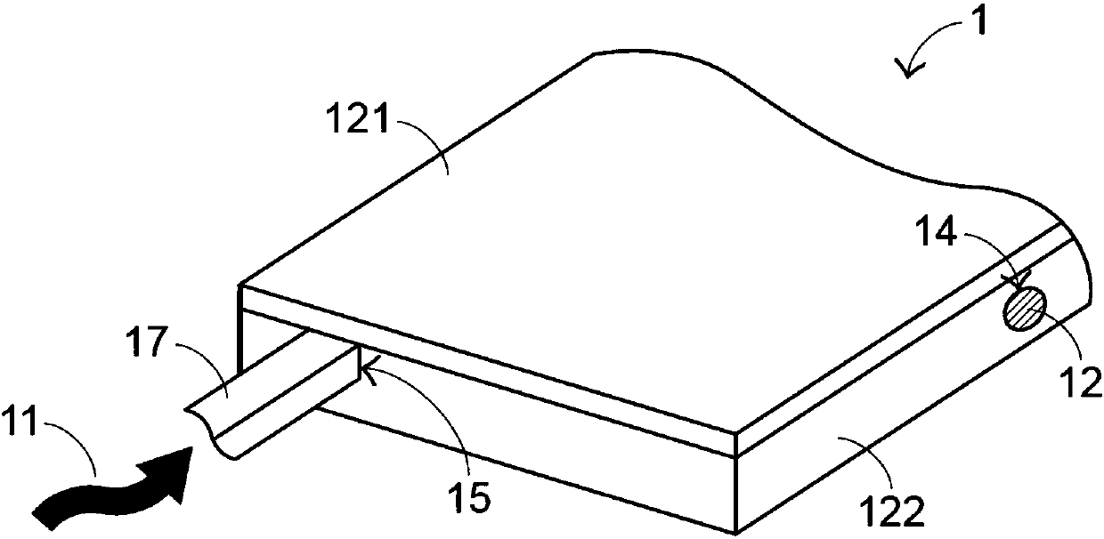
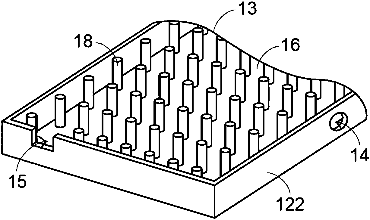
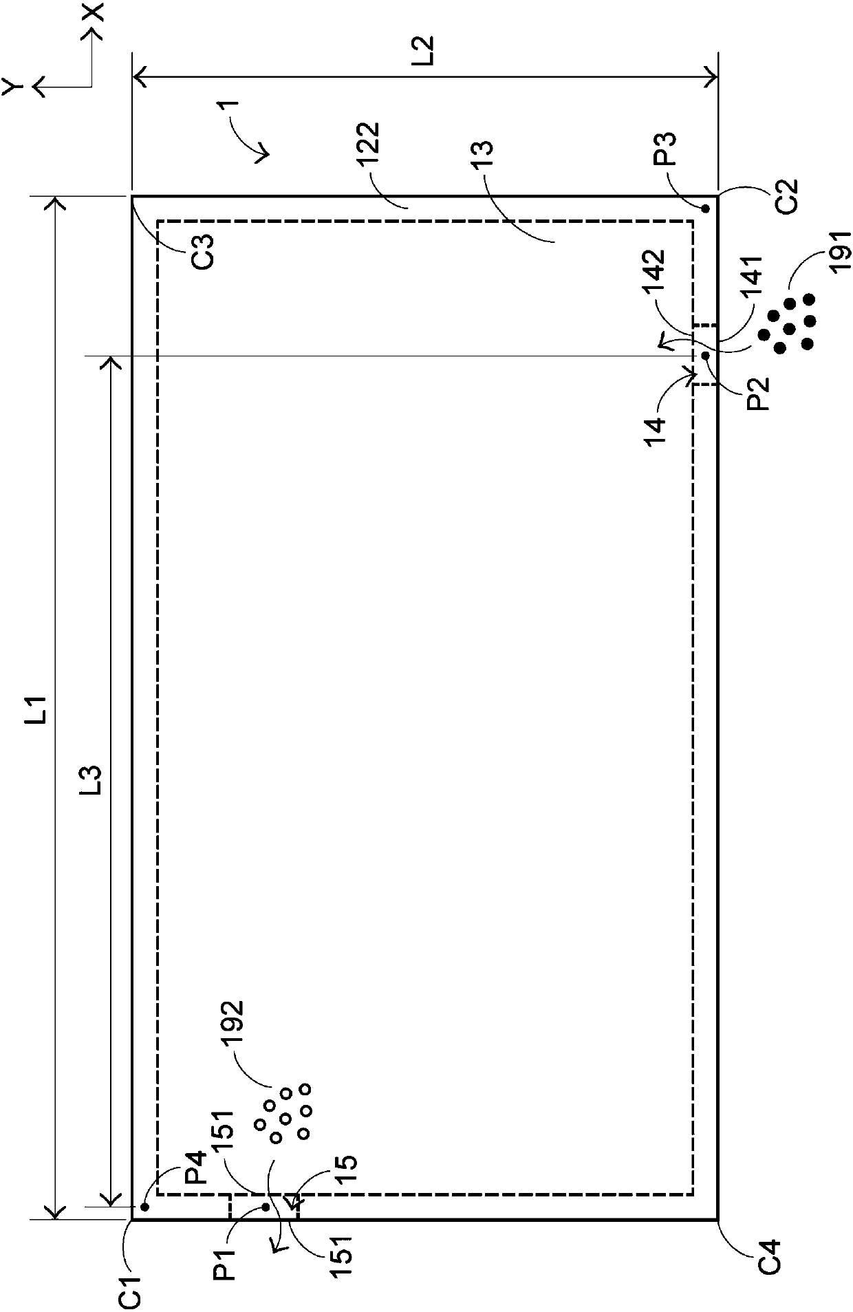
[0043] see Figure 1 ~ Figure 3 , figure 1 It is a schematic diagram of the appearance structure of a first preferred embodiment of the vapor chamber of the present invention, figure 2 for figure 1 The partial structural schematic diagram of the vapor chamber shown, image 3 for figure 1 The top view conceptual schematic diagram of the partial structure of the vapor chamber shown. For clarity, figure 2 and image 3Components such as the upper plate are not shown in the figure. The vapor chamber 1 includes an upper plate body 121 and a lower plate body 122, both of which together form a chamber 13, and the se...
PUM
 Abstract
Description
Claims
Application Information