Motor

A technology for motors and resin parts, applied in the field of motors, can solve problems such as adverse effects of control parts, achieve the effect of suppressing impeller shaking and ensuring cooling performance

Inactive Publication Date: 2018-12-21
NIDEC CORP
View PDF4 Cites 0 Cited by
  • Summary
  • Abstract
  • Description
  • Claims
  • Application Information

AI Technical Summary

Problems solved by technology

Therefore, the heat generated from the motor during drivi

Method used


Image

  • Motor
  • Motor
  • Motor

Examples


Example Embodiment

[0024] Below, while referring to the appendix Figure 1 The motor of the present invention will now be described in detail. In this manual, the Figure 4 The direction in which the shown central axis A of the motor extends is abbreviated as "axial", and the radial and circumferential directions centered on the central axis A of the motor are simply referred to as "radial" and "circumferential". Also for the impeller attached to the motor, the directions corresponding to the axial direction, the radial direction, and the circumferential direction of the motor are simply referred to as "axial direction", "radial direction", and "circumferential direction".

[0025]

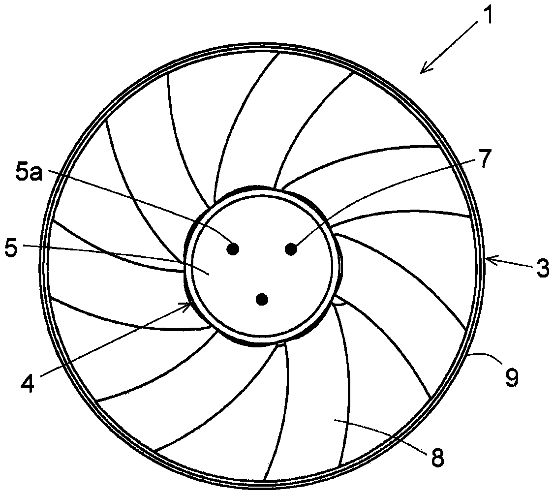
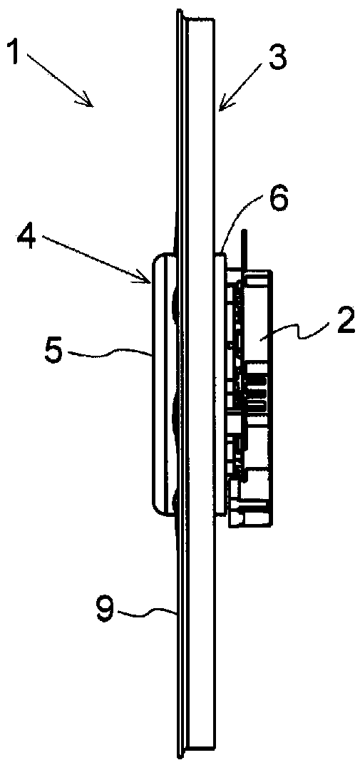
[0026] figure 1 It is a schematic plan view which shows the electric fan 1 of this embodiment. figure 2 It is a schematic side view which shows the electric fan 1 of this embodiment. The electric fan 1 has a motor 2 and an impeller 3 . The impeller 3 is attached to the motor 2 via a protruding portion 130 , ...


PUM


Abstract

This motor is an inner rotor-type motor, and is provided with: a rotor which rotates around a central axis; and a stator which is positioned outside the rotor in the radial direction. The rotor is provided with a rotor core, and a resin part which covers at least a portion of the rotor core. The rotor core is provided with a plurality of through holes which pass therethrough in the axial direction. The resin part is provided with: a first resin part which covers at least a portion of the end surface of the rotor core at one side in the axial direction; and an extension part which is provided to at least one of the plurality of through holes, and which extends from the first resin part into the through hole in the axial direction. The first resin part is provided with a protruded part whichprotrudes towards the one side in the axial direction. The protruded part and the extension part overlap in a planar view from the axial direction.

Description

technical field [0001] This invention relates to motors. Background technique [0002] In recent years, for the sake of downsizing, a motor and a control unit for controlling the motor have been assembled into one unit. When the motor and the control unit are unitized, the distance between the motor and the control board of the control unit is shortened. Therefore, heat generated from the motor during driving may adversely affect the operation of the control unit. [0003] For example, Patent Document 1 discloses a structure in which, in an inner rotor type motor, the motor is cooled by the flow of air generated by the rotation of the rotor. In the motor of Patent Document 1, two types of air guides are formed on the end surface of the rotor opposite to the side where the impeller is provided. [0004] prior art literature [0005] patent documents [0006] Patent Document 1: Specification of US Patent Application Publication No. 2014 / 0191623 Contents of the invention...

Claims


Application Information

Patent Timeline
IPC IPC(8): H02K9/02H02K9/06
CPCH02K9/02H02K9/06H02K1/30H02K7/14H02K15/12H02K1/276H02K1/32H02K2213/03H02K1/28H02K11/30F04D19/002F04D29/181H02K5/1732H02K5/225H02K7/083H02K21/16H02K2211/03
Inventor 梅田智之右田贵之
Owner NIDEC CORP
Why Eureka
Try Eureka