Steel rail roller conveyer

A technology of conveyors and rollers, which is applied in the direction of rollers, mechanical equipment, transportation and packaging, etc., can solve the problems of complex structure, large volume, removal, etc., and achieve the effect of compact structure, small volume and high rigidity

Inactive Publication Date: 2008-09-03
中国铁路呼和浩特局集团有限公司焊轨段
View PDF0 Cites 13 Cited by
  • Summary
  • Abstract
  • Description
  • Claims
  • Application Information

AI Technical Summary

Problems solved by technology

The problem with this structure is that when the rail needs to be lifted off the roller table line, the horizontal rollers pressing on the head of the rail must be removed
However, this structure is more complex and bulky, which reduces the area of ​​the 500-meter long rail storage platform for storing rails, and has a relatively large defect in the use of the 500-meter long rail storage platform.

Method used


Image

  • Steel rail roller conveyer
  • Steel rail roller conveyer

Examples


Embodiment Construction

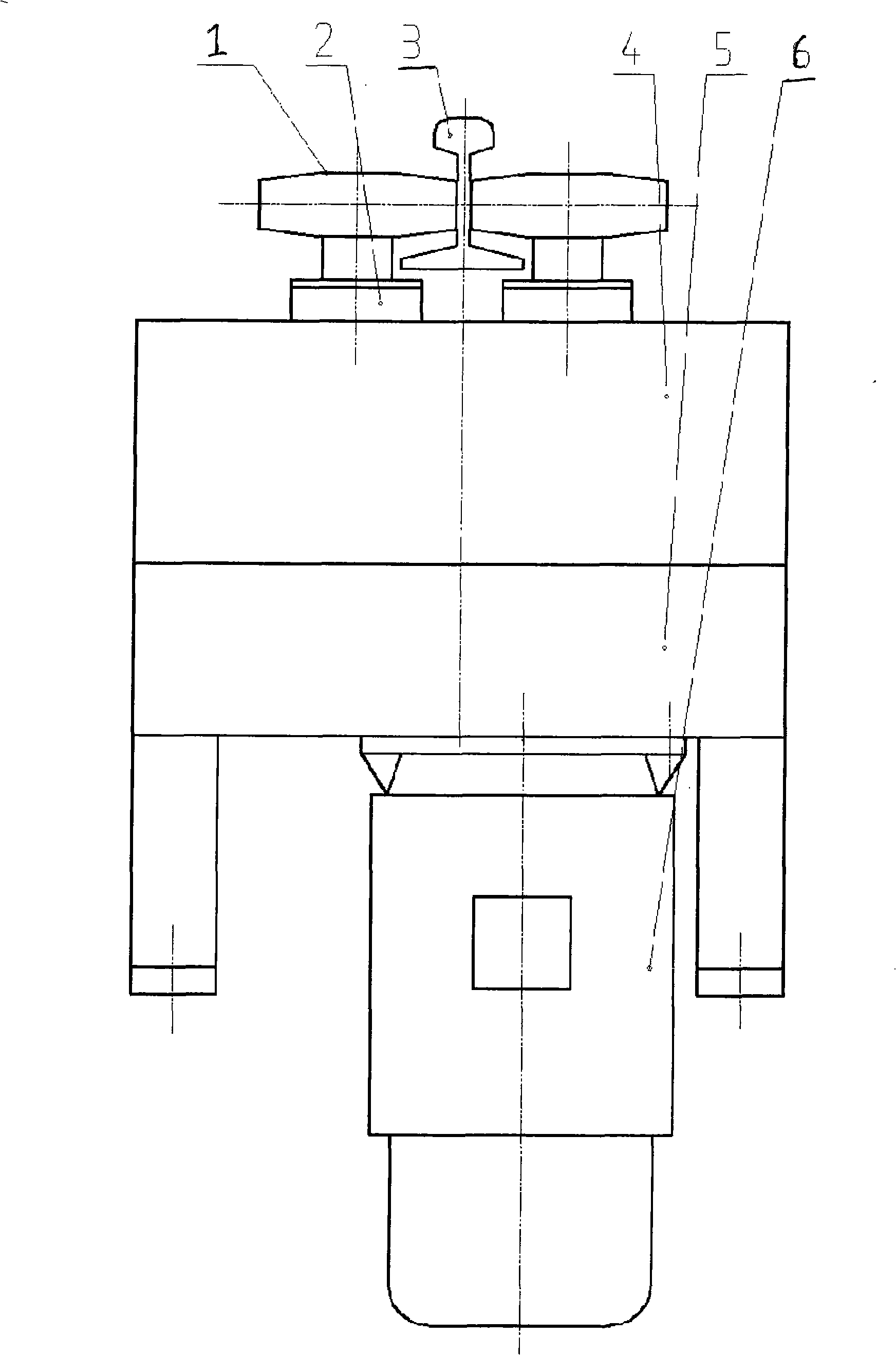
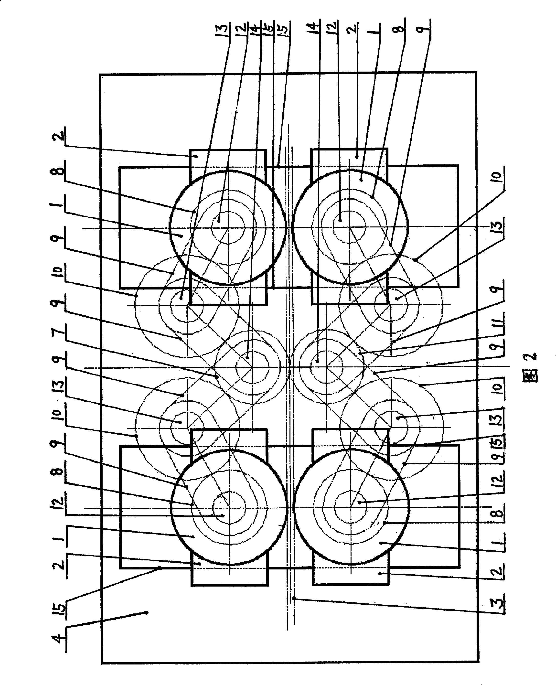
[0008] Below in conjunction with accompanying drawing, the present invention will be further described: figure 1 , shown in Fig. 2, two pairs of driving vertical rollers 1 clamp the rail waist 3, and the motor 6 transmits power to the opening and closing driving vertical roller box 4 through the reduction box 5. As shown in Figure 2, in the opening and closing driving vertical roller box 4, the gears 7, 8, 10, 11 are meshed with each other, and the intermediate gear shaft 13 is respectively connected with the rotating arm 9 on the driving vertical roller main shaft 12 and the fixed transmission shaft 14. Rotary arm 9 is hinged. Each driving vertical roller main shaft 12 forms a gear-link mechanism with the fixed transmission shaft 14 respectively, and four driving vertical roller main shaft boxes 2 are independent casings and have a closed guide rail structure. Gears 7 and 11 are fixed in position. Due to the principle of the gear-link mechanism, the driving vertical roller ...


PUM


Abstract

The invention discloses a steel rail roller conveyor. The main structure of the conveyor is that a motor is engaged with a gear fixed in the lower part of a transmission shaft inside a driving vertical roll cabinet through a retarder, a pair of gears fixed in the middle part of a stationary transmission shaft are engaged with each other and respectively engaged with two groups of intermediate gears, the intermediate gears are engaged with the gear in the middle part of a driving vertical roll to drive the rotation of the driving vertical roll, each intermediate gear is respectively engaged with a pivoted arm on the main shaft of the driving vertical roll and a pivot arm on the stationary transmission shaft, each main shaft of the driving vertical roll respectively forms a gear-link rod mechanism together with the stationary transmission shaft, and the four driving vertical roll cabinets are independent and have closed guide track structure. The inventive steel rail roller conveyor realizes the rotation of two pairs of driving vertical rolls for holding the rail web at the same rotation speed. The driving vertical rolls convey long steel rails to the 500-meter long steel rail storage platform along a roller line and then open to make room for hoisting the steel rails, so as to meet the technical requirements of driving the steel rails to travel along the roller line of the 500-meter long steel rail storage platform.

Description

technical field [0001] The invention relates to a rail roller conveyor, in particular to a rail roller conveyor which is specially used for driving the rail roller in a railway fixed-length rail welding production line. Background technique [0002] At present, the structure of the existing rail roller conveyor is that the reducer rotates the lower horizontal drive roller, which is driven by friction with the rail bottom; the rail head has an upper horizontal roller that can swing or move, and the upper horizontal roller is driven by air pressure or hydraulic pressure. The roller is pressed on the head of the rail to increase the friction between the lower horizontal driving roller and the bottom of the rail to realize the driving of the rail roller table in the rail welding production line. The problem with this construction is that when the rail needs to be hoisted off the roller table line, the horizontal rollers pressing on the head of the rail must be moved away. If th...

Claims


Application Information

Patent Timeline
Patent Type & Authority Applications(China)
IPC IPC(8): B65G13/06F16H37/12
Inventor 蔡庄厚徐其瑞方师敬郭晋龙赵子龙刘伟郭俊文罗询王永富闫存祯
Owner 中国铁路呼和浩特局集团有限公司焊轨段
Why Eureka
Try Eureka