Paper winder and working method thereof

A paper winding machine and rolling paper technology, which is applied in the direction of winding strips, thin material processing, transportation and packaging, etc., can solve the problems affecting the normal production of the paper machine and the increase of the speed of the machine, affecting the time of changing rolls, and affecting the safety of the paper tail and other issues, to achieve the effect of ensuring the quality of high-speed paper, ensuring safe work, and ensuring the speed of the vehicle

Active Publication Date: 2008-09-03
NINGBO ASIA PULP & PAPER
View PDF0 Cites 4 Cited by
  • Summary
  • Abstract
  • Description
  • Claims
  • Application Information

AI Technical Summary

Problems solved by technology

However, the speed increase is limited by various conditions, especially in the case of high speed, the finished paper roll will generate a large centrifugal force when the roll is changed, and when the mandrel brakes to stop when producing smooth paper, The outer layer of the finished paper roll is still running due to the inertial centrifugal force, resulting in the loosening of the finished paper roll, which seriously affects the normal production of the paper machine and the increase of the speed of the machine, and at the same time produces a lot of loss; in addition, the tail of the paper is shaken when the roll is changed. also seriously affect safety
At present, the method of prolonging the braking time is often used to solve this problem, but it affects the time of changing rolls. At the same time, it is necessary to limit the speed of the machine to ensure the normal operation of the paper machine, which also affects the increase of the speed of the paper machine. A breakthrough in production capacity

Method used


Image

  • Paper winder and working method thereof
  • Paper winder and working method thereof

Examples


Embodiment Construction

[0021] The present invention will be further described in detail below in conjunction with the accompanying drawings and embodiments.

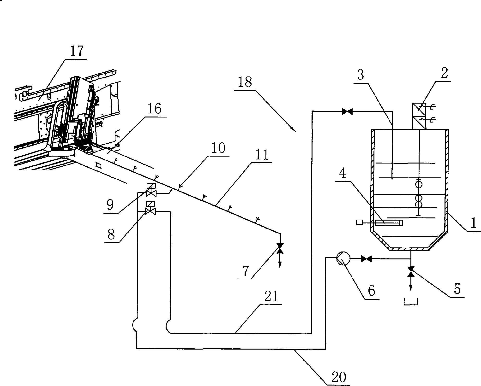
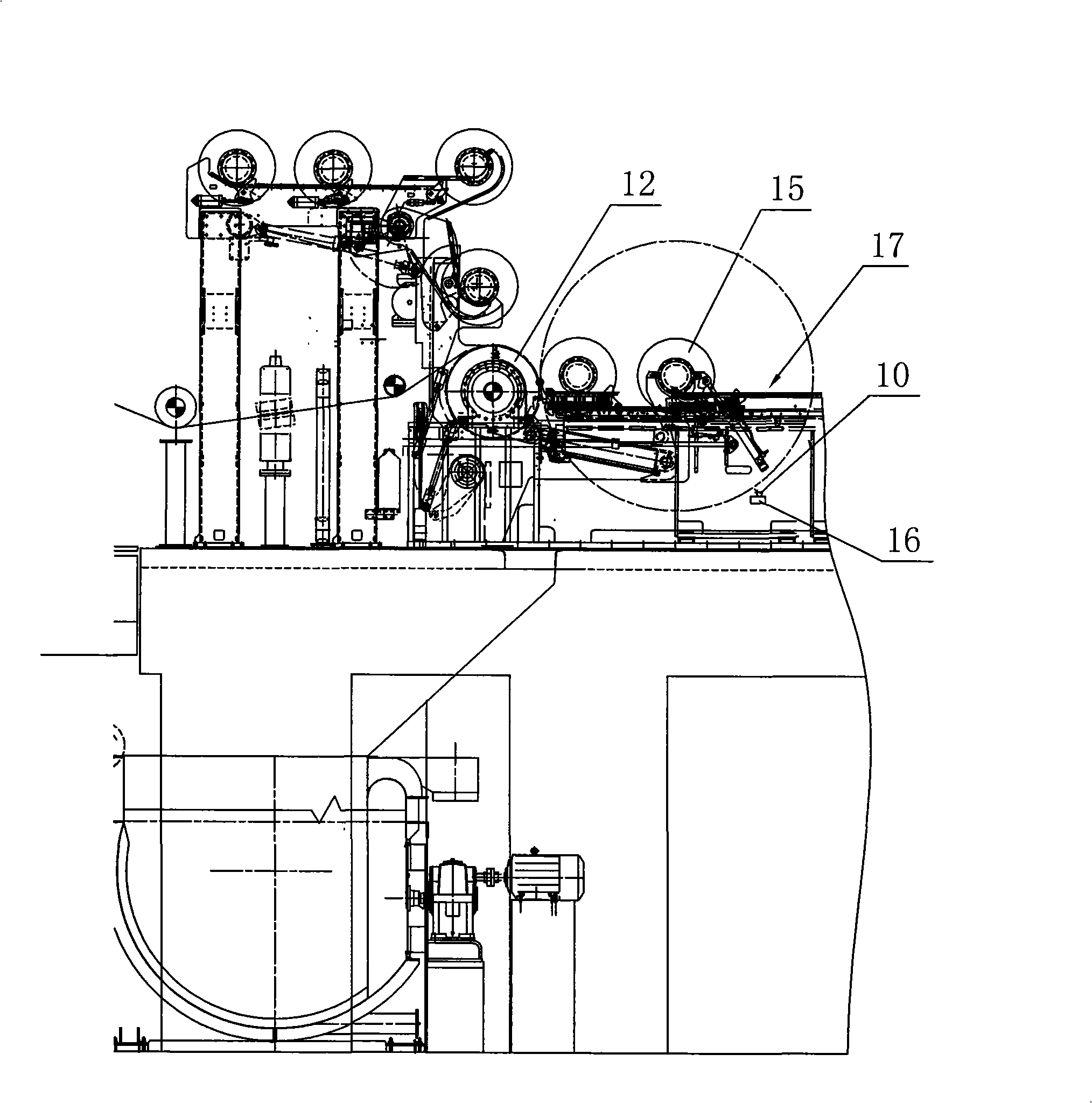
[0022] As shown in the figure, a paper reel includes a workbench 17 on which a reel cylinder 12, a roll change iron core 15 and a loading brake device 16 are arranged. The glue spraying system 18 whose end is bonded to the surface of the paper roll, the glue spraying system 18 includes a glue bucket 1 for holding the glue, a glue spray valve 9, an automatic backflow valve 8 and a plurality of nozzles connected with each other by pipes 11 10. The pipeline 11 is fixedly installed on the loading brake device 16, the pipeline 11 is provided with a cleaning valve 7, the bottom of the rubber barrel 1 is provided with a discharge pipe 20, and a pump 6 is provided on the discharge pipe 20, and the pump 6 passes through the glue spray The valve 9 is connected with the nozzle 10, the pump 6 is connected with the return automatic valve 8 at the same time...


PUM


Abstract

The invention discloses a paper winder, comprising a workbench and a reel cylinder, a paper roll alternation iron core and a loading braking device arranged on the workbench. The paper winder is characterized in that the paper winder also comprises a glue spraying system for gluing the end of a paper roll on the surface of the paper roll when changing the paper roll. Because of the glue spraying system arranged around the paper roll-changing iron core of the paper winder, which can spray glue on paper surface 6 seconds before changing the paper roll to glue the end of the paper roll on the surface of the paper roll so as to completely solve the problem which the paper roll gets loose under the action of inertial centrifugal force and at the same time solve the problem which the end paper swings after changing the paper roll, thereby ensuring the increase of paper machine speed and the paper quality under the high paper machine speed. Because of a temperature controlled heater arranged on a glue barrel, which can control the glue temperature at about 50 DEG C, the fluidity of the glue is ensured. Furthermore, a liquid level alarm is arranged on the glue barrel and used for alarming when the liquid level is lower than a preset value until the operation is stopped, so as to ensure the safe operation of the temperature-controlled heater and the pumps.

Description

technical field [0001] The invention relates to a paper winding machine, in particular to a paper winding machine and its working method. Background technique [0002] With the rapid development of international large-scale paper machines, the improvement of machine speed has become the goal pursued by international famous paper equipment manufacturers and production plants such as Metso and Voith. However, the speed increase is limited by various conditions, especially in the case of high speed, the finished paper roll will generate a large centrifugal force when the roll is changed, and when the mandrel brakes to stop when producing smooth paper, The outer layer of the finished paper roll is still running due to the inertial centrifugal force, resulting in the loosening of the finished paper roll, which seriously affects the normal production of the paper machine and the increase of the speed of the machine, and at the same time produces a lot of loss; in addition, the tai...

Claims


Application Information

Patent Timeline
Patent Type & Authority Applications(China)
IPC IPC(8): B65H19/29B65H19/00
Inventor 陈小东胡波张国宝姜正友陆柏春王林东
Owner NINGBO ASIA PULP & PAPER
Why Eureka
Try Eureka