
Method and apparatus for controlling central air-conditioning end supply backwater temperature difference

A technology of temperature difference between supply and return water and central air-conditioning, applied in space heating and ventilation, heating and ventilation control systems, household heating, etc. Too big and other issues

Active Publication Date: 2008-09-03
广东新菱空调科技有限公司
View PDF0 Cites 45 Cited by
  • Summary
  • Abstract
  • Description
  • Claims
  • Application Information

AI Technical Summary

Problems solved by technology

[0005]According to this control method in the prior art, although it can basically meet the requirements of the comfort of the air conditioner, it is only controlled according to the set value of the room temperature to meet the needs of the indoor environment. Temperature demand, when the indoor temperature setting value of many air-conditioning terminal refrigeration equipment is unreasonable, for example, when the set room temperature setting value is far lower than the actual demand, the opening of the terminal refrigeration equipment regulating valve is too large , some control valves are even at 100% opening, resulting in a situation where the flow rate of the chilled water pump is too large, resulting in a temperature difference between the supply and return water flowing through the terminal refrigeration equipment that is much lower than the normal temperature range, and the temperature difference is extremely unstable
In addition, the lower temperature difference between supply and return water requires a larger flow rate of chilled water. If things go on like this, the chilled water pump will consume more electricity
[0006]The above situation may even lead to hydraulic imbalance of the central air-conditioning system when it is more serious, resulting in uneven cooling and heating of the system cooling effect, resulting in the current situation of high energy consumption of central air-conditioning

Method used


Image

  • Method and apparatus for controlling central air-conditioning end supply backwater temperature difference
  • Method and apparatus for controlling central air-conditioning end supply backwater temperature difference
  • Method and apparatus for controlling central air-conditioning end supply backwater temperature difference

Examples


Embodiment 1

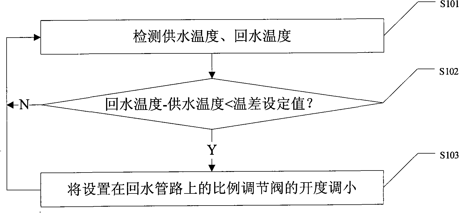
[0035] Such as figure 1 Shown is a schematic flow chart of Embodiment 1 of the method for controlling the temperature difference between supply and return water at the terminal of a central air conditioner in the present invention. In this embodiment, the terminal equipment of the central air conditioner has already met the requirement of the set value of the room temperature.

[0036] Such as figure 1 Shown, in the present embodiment, method of the present invention comprises steps:

[0037] Step S101: Detect the supply water temperature in the water supply pipeline and the return water temperature in the return water pipeline, and proceed to step S102;

[0038] Step S102: Determine whether the difference between the return water temperature minus the supply water temperature is less than the temperature difference set value, if yes, go to step S103, if not, do not take any action, or return to step S101 to continue detection afterward or after a period of time, According ...

Embodiment 2

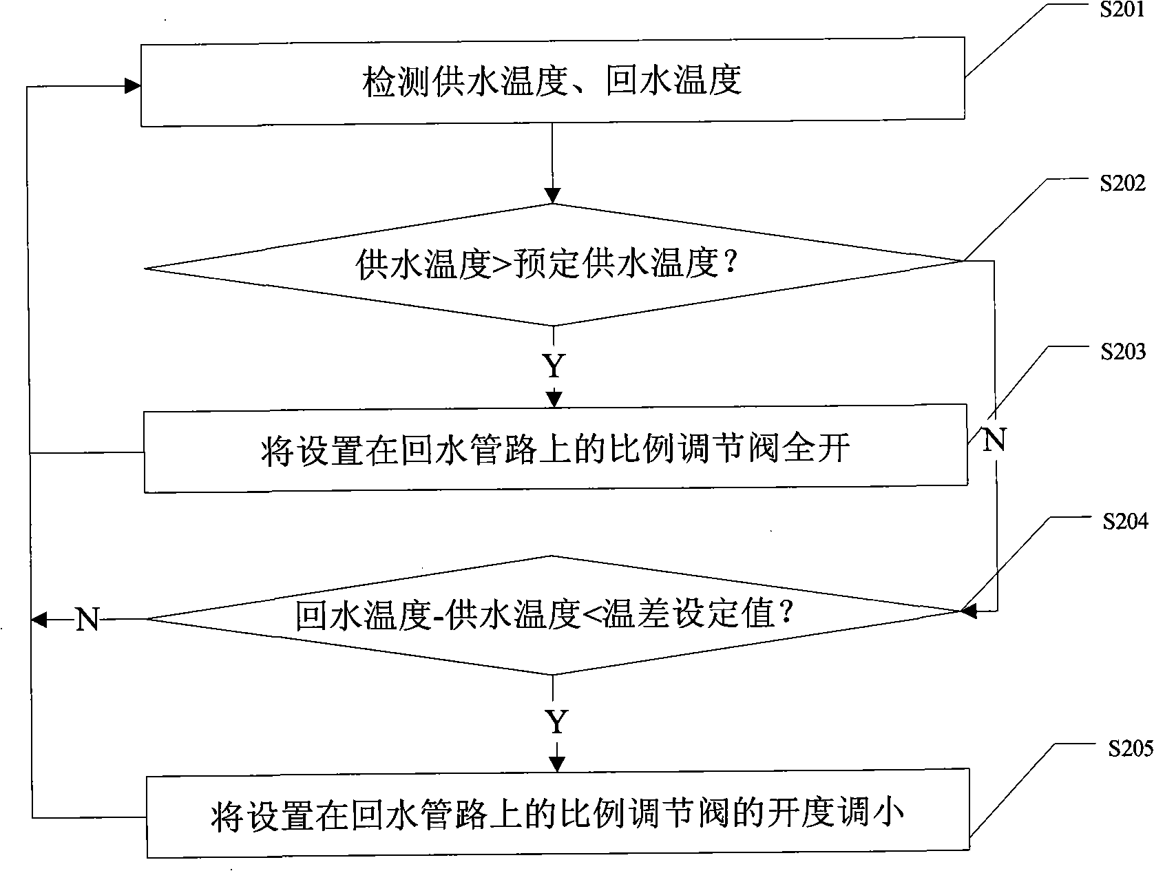
[0044] Such as figure 2Shown is a schematic flow chart of Embodiment 2 of the method for controlling the temperature difference between supply and return water at the terminal of a central air conditioner in the present invention. In this embodiment, the main difference from Embodiment 1 is that in the method of this embodiment, the temperature of the water supply on the water supply pipeline is prioritized for determination.

[0045] Such as figure 2 As shown, in this embodiment, the method in this embodiment includes steps:

[0046] Step S201: Detect the supply water temperature in the water supply pipeline and the return water temperature in the return water pipeline, and proceed to step S202;

[0047] Step S202: Determine whether the water supply temperature is higher than the predetermined water supply temperature, if yes, go to step S203, if not, go to step S204;

[0048] Step S203: Control fully opening the proportional regulating valve set on the return water pipe...

Embodiment 3

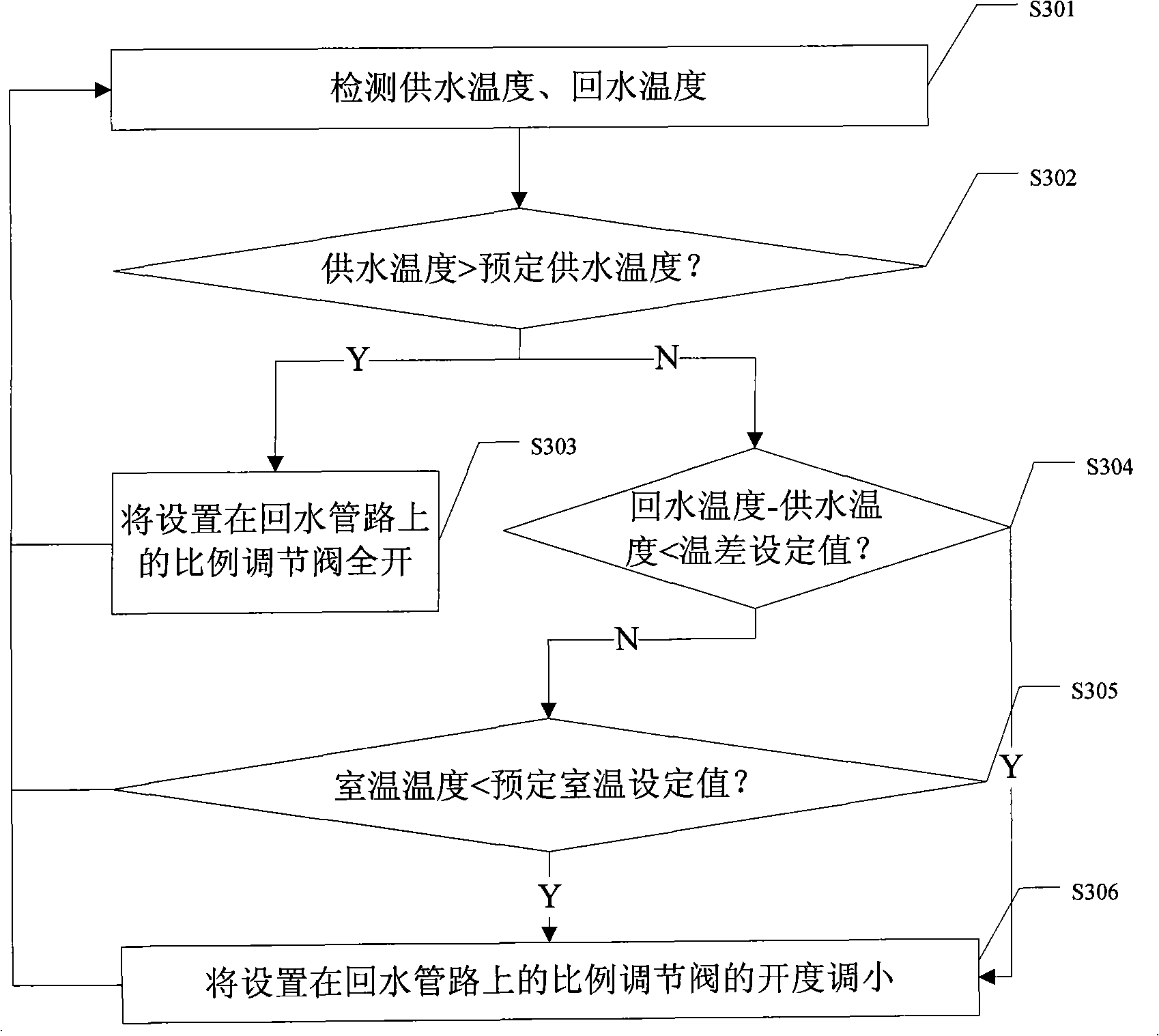
[0055] Such as image 3 As shown, it is a schematic flow chart of the third embodiment of the method for controlling the temperature difference between the supply and return water at the end of the central air conditioner according to the present invention. In this embodiment, the difference from the second embodiment mainly lies in the addition of Steps for judging whether the room temperature meets the predetermined requirements.

[0056] Such as image 3 Shown, in the present embodiment, method of the present invention comprises steps:

[0057] Step S301: Detect the supply water temperature in the water supply pipeline and the return water temperature in the return water pipeline, and proceed to step S302;

[0058] Step S302: Determine whether the water supply temperature is greater than the predetermined water supply temperature, if yes, go to step S303, if not, go to step S304;

[0059] Step S303: Control the full opening of the proportional regulating valve set on the...


PUM


Abstract

A method and a device for controlling temperature difference between the supplied water and the back water at the end of a central air conditioner are disclosed. According to a received detected supplied water temperature signal value of the water supply pipe line and a back water temperature signal value of the back water pipe line, the differential value between the back water temperature signal value and the supplied water temperature signal value is compared with a preset temperature value. Opening of a ratio regulating valve disposed on the back water pipe line is adjusted according to the comparative result and preset conditions. The opening of the ration regulating valve is turned smaller to decrease back water flow based on the differential value between the back water temperature and the supplied water temperature and the preset temperature differential value. After operating for a while, the temperature difference between the supplied water and the back water is bigger than or equal to the preset temperature value. In a precondition that the temperature satisfies the preset requirements, room temperature control requirement is satisfied based on a preset room temperature value.

Description

technical field [0001] The invention relates to the central air-conditioning refrigeration technology, in particular to a method and a device for controlling the temperature difference between supply and return water at the end of the central air-conditioning in the central air-conditioning refrigeration technology. Background technique [0002] With the development of urban construction, building energy consumption has accounted for a relatively large proportion of the country's total energy consumption, and in building energy consumption, air-conditioning energy consumption accounts for a large proportion, and it is showing a rising trend, especially in In summer during the peak period of urban electricity consumption, the power consumption of central air-conditioning accounts for 30% of the total power generation, and it reaches more than 50% in developed areas in southern China. Therefore, the energy-saving design of central air-conditioning is increasingly important and ...

Claims


Application Information

Patent Timeline
Patent Type & Authority Applications(China)
IPC IPC(8): F24F11/00
Inventor 谭文胜
Owner 广东新菱空调科技有限公司
Learn More