Control method and system for mobile spectral filter

A control method and technology for a control system, applied in the field of photoelectric imaging, can solve the problems that the moving filter is prone to malfunction, and the working state of the switching of the moving filter cannot be reflected, so as to save design costs, meet real needs, and avoid The effect of malfunction

Inactive Publication Date: 2008-09-03
SHENZHEN COSHIP ELECTRONICS CO LTD
View PDF0 Cites 10 Cited by
  • Summary
  • Abstract
  • Description
  • Claims
  • Application Information

AI Technical Summary

Problems solved by technology

[0005] The purpose of the embodiments of the present invention is to provide a control method and system for a mobile filter, aiming at solving the problem that in the prior art, when switching the mobile filter, it is easy to cause misoperation and the working state of the mobile filter switching cannot reflect the user's question of true will

Method used


Image

  • Control method and system for mobile spectral filter
  • Control method and system for mobile spectral filter
  • Control method and system for mobile spectral filter

Examples


Embodiment Construction

[0029] In order to make the object, technical solution and advantages of the present invention clearer, the present invention will be further described in detail below in conjunction with the accompanying drawings and embodiments. It should be understood that the specific embodiments described here are only used to explain the present invention, not to limit the present invention.

[0030] By judging the working state of the mobile filter set by the user, the present invention implements the operation of closing, opening or automatic control on the mobile filter, so that the mobile filter can accurately operate according to the user's wish.

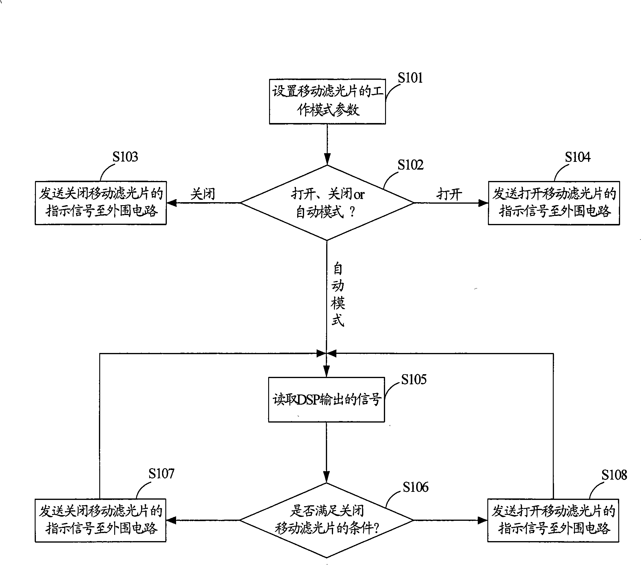
[0031] Please refer to figure 1 , the implementation process of controlling the action of moving the optical filter provided by the embodiment of the present invention is described in detail as follows.

[0032] In step S101, the user sets the working mode parameters of the moving filter.

[0033] In the embodiment provided by the prese...


PUM


Abstract

The invention provides a control method and system of removal filter, suitable for photoelectric imaging field, comprising setting work mode of removal filter; performing the command of turning on, off the removal filter or automatically switching the work state of the removal filter, based on the work mode of the filter. The invention can save the design cost of part of the periphery circuit and prevents the error action of removal filter resulted from the random fluctuation of illumination condition in short time, at the same time the work mode parameter of filter is set as automation mode, and the switching condition can be preset by user and when and how to switching the removal filter is flexibly realized, to satisfy the real requirement of the user.

Description

technical field [0001] The invention belongs to the field of photoelectric imaging, and in particular relates to a control method and system for moving an optical filter. Background technique [0002] The alias of the filter is Optical Low Pass Filter (OLPF), and its main function is to correct the incoming light of the Charge Coupled Device (CCD) and filter out the infrared light entering the color CCD. As far as the latter function of OLPF is concerned, CCD does not need to filter infrared rays under any circumstances. For example, when the lighting conditions are relatively poor, in order to obtain a clearer image, it is necessary to make the CCD feel as much light as possible to be able to perceive Infrared light, in this case, can no longer use filters; another opposite situation is when the lighting conditions are better, CCD can produce better images without infrared rays, in this case, if The CCD senses the infrared light, which will cause the color shift of the ima...

Claims


Application Information

Patent Timeline
Patent Type & Authority Applications(China)
IPC IPC(8): G03B17/14H04N5/232
Inventor 段玉仁王庆华
Owner SHENZHEN COSHIP ELECTRONICS CO LTD
Why Eureka
Try Eureka