Method for pretesting and forecasting ion beam polishing process result

A technology of ion beams and processes, applied in special data processing applications, instruments, electrical digital data processing, etc., can solve the problems of complex calculations in the forecasting process and lack of forecasting

Inactive Publication Date: 2008-09-03
NAT UNIV OF DEFENSE TECH
View PDF0 Cites 11 Cited by
  • Summary
  • Abstract
  • Description
  • Claims
  • Application Information

AI Technical Summary

Problems solved by technology

The advantage of this method is that the prediction results are intuitive and reliable, but the disadvantage is that the calculation of the prediction process is complicated, and

Method used


Image

  • Method for pretesting and forecasting ion beam polishing process result
  • Method for pretesting and forecasting ion beam polishing process result
  • Method for pretesting and forecasting ion beam polishing process result

Examples


Example Embodiment

[0037] Example

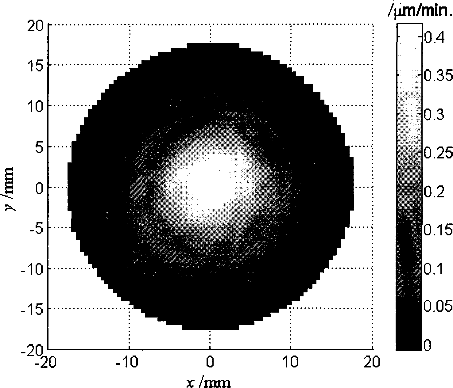
[0038] The ion beam polishing process of this embodiment is carried out on an ordinary ion beam polishing equipment, and the process parameters are: the working gas is argon, and the working vacuum is 0.8×10 -2 Pa, ion energy 1100eV, beam current 25mA. The test workpiece to be polished is a 100mm diameter ordinary glass-ceramic that has been traditionally polished. The method of the present invention is used to predict the result of the 100mm diameter ordinary glass-ceramic processed by the ion beam polishing process. The specific steps of the method are as follows:

[0039] 1. Determine the removal function of the polishing process: use the ion beam polishing process under the above process parameters to perform the removal function test to obtain the removal function: the removal function test time is 1 minute, and the obtained removal function test result p(x, y) is as follows figure 1 Shown

[0040] 2. Determine the equivalent filter unit impulse response fun...


PUM


Abstract

The invention discloses a method for predicting a manufacture result of ion beam polishing according to consistency on mathematic model in a modification processing course and a dimension filtering course. The method firstly confirms a removal function of polishing process, then confirms an equivalent low pass filter pulse response function according to the removal function, detects error for a optical mirror by using face form detection device, calculates face form residual according to the detected face form error and the filter pulse respond function, realizes a prediction of ion beam polishing processing result according to the calculated face form residual. On this basis, the method also can predict variance situation of each space frequency component before and after the processing according to the filter pulse respond function. The predictor method of the invention is more easy and maneuverable, and the prediction result is more visual reliable and all-round.

Description

technical field [0001] The invention belongs to the field of optical processing, in particular to a method for predicting and forecasting processing results in a polishing process. Background technique [0002] In the ion beam modification processing technology, the current prediction method of processing results is based on the simulation method of virtual processing. This method first calculates the dwell time, and then performs virtual processing to calculate the residual error distribution of virtual processing. The advantage of this method is that the prediction result is intuitive and reliable, but the disadvantage is that the calculation of the prediction process is complex, and the dwell time needs to be calculated first, and the prediction method lacks the prediction and prediction of the change of each frequency component in the processing process. Contents of the invention [0003] The technical problem to be solved by the present invention is to overcome the de...

Claims


Application Information

Patent Timeline
IPC IPC(8): G06F17/00C03C23/00
Inventor 解旭辉李圣怡戴一帆周林焦长君陈善勇王贵林
Owner NAT UNIV OF DEFENSE TECH
Why Eureka
Try Eureka